YG12_英文保养手册.pdf - 第97页
Appendix Appendix Contents 1. Specifications A- 1 1.1 Air regulator unit A- 1 1.2 Power connection terminals A- 2
4-11
4
How to replace consumable parts
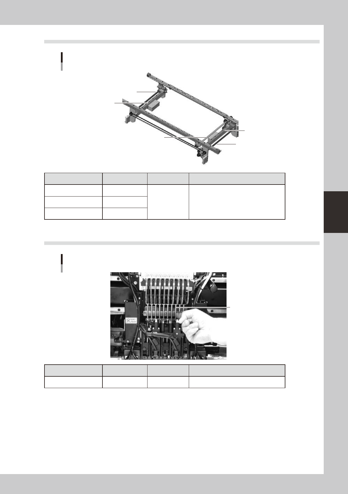
6.4 Conveyor W-axis linear guide and ball screw
W-axis lubrication points
W-axis ball screw
W-axis ball screw
Hexagonal spline
W-axis linear guide
W-axis linear guide
Lubrication section Lubrication point Interval Procedure
Linear guide 2
Once a month Apply grease by hand.Ball screw 2
Hexagonal spline 1
53438-L5-00
6.5 Head spline shaft
Z-axis lubrication points
Z-axis spline shaft
Lubrication section Lubrication point Interval Procedure
Z-axis spline shaft 10 3 months Apply a thin coat of grease by hand.
53439-L5-00

A-1
Appendix
1. Specifications
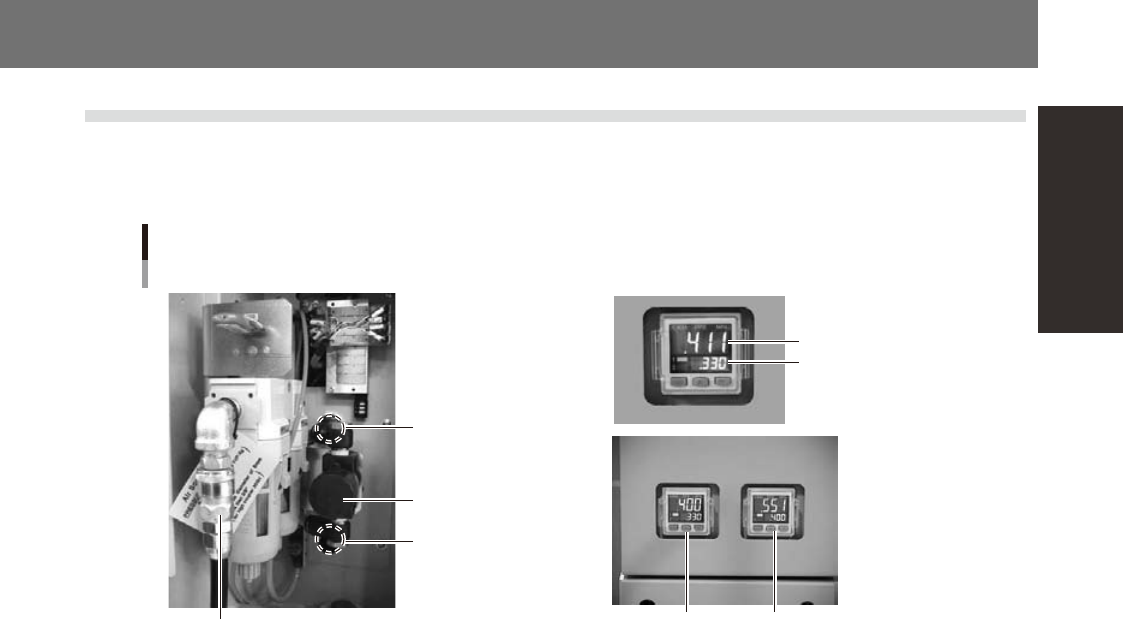
1.1 Air regulator unit
The air regulator for controlling the air pressure to the pneumatic units of the machine is located behind the
front lower left panel. A digital pressure gauge is provided on the front left of the machine. The air pressure
must be set to the optimum level.
Air pressure regulator
for machine
Air pressure regulator
for head (YG12)
Air supply/shutoff
switch (valve)
Source air connector
Air pressure regulator and pressure gauge
Air pressure setting
for machine
Pressure-drop
detection level
Air pressure setting for machineAir pressure setting for head
YS12
YG12
53427-L5-00
■
Supply air pressure
This is the pressure of the source air supplied to the machine. Before setting the air pressure with the air regulator, make
sure that this supply air pressure is in the following optimal range.
YS12 : 0.45MPa to 0.70MPa
YG12 : 0.60MPa to 0.70MPa
■
Digital pressure gauge
Shows the supply air pressure (upper reading) and pressure-drop detection level (lower reading). A normal pressure value
is shown in green, and a pressure value lower than the pressure-drop detection level is shown in red.
■
Air pressure setting and pressure-drop detection level
• YS12
Air pressure setting for machine (upper reading) : 0.40MPa
Pressure-drop detection level (lower reading) : 0.33MPa
• YG12
Air pressure setting for machine (upper reading on right pressure gauge) : 0.55MPa
Pressure-drop detection level (lower reading on right pressure gauge) : 0.40MPa
Air pressure setting for head (upper reading on left pressure gauge) : 0.40MPa to 0.41MPa
Pressure-drop detection level (lower reading on left pressure gauge) : 0.33MPa
■
Air supply/shutoff switch (valve)
Turning this switch to the right shuts off air supply and exhausts air that remains inside the machine.
■
Source air connector
Prepare an air hose with an inner diameter of at least 8mm having a 40SH socket (Nitto Koki, or equivalent), and connect
it to this connector. Use dry, clean air passed through an air filter.