YG12_英文保养手册.pdf - 第90页
4-5 4 How to replace consumable parts 3.3 Replacing the cleaning blow valve 1 T urn off the air supply and the pow er to the machine. Quit the software and turn off the machine power switch. Then turn the air supply/ shu…
4-4
4
How to replace consumable parts
3.2 Replacing a solenoid coil
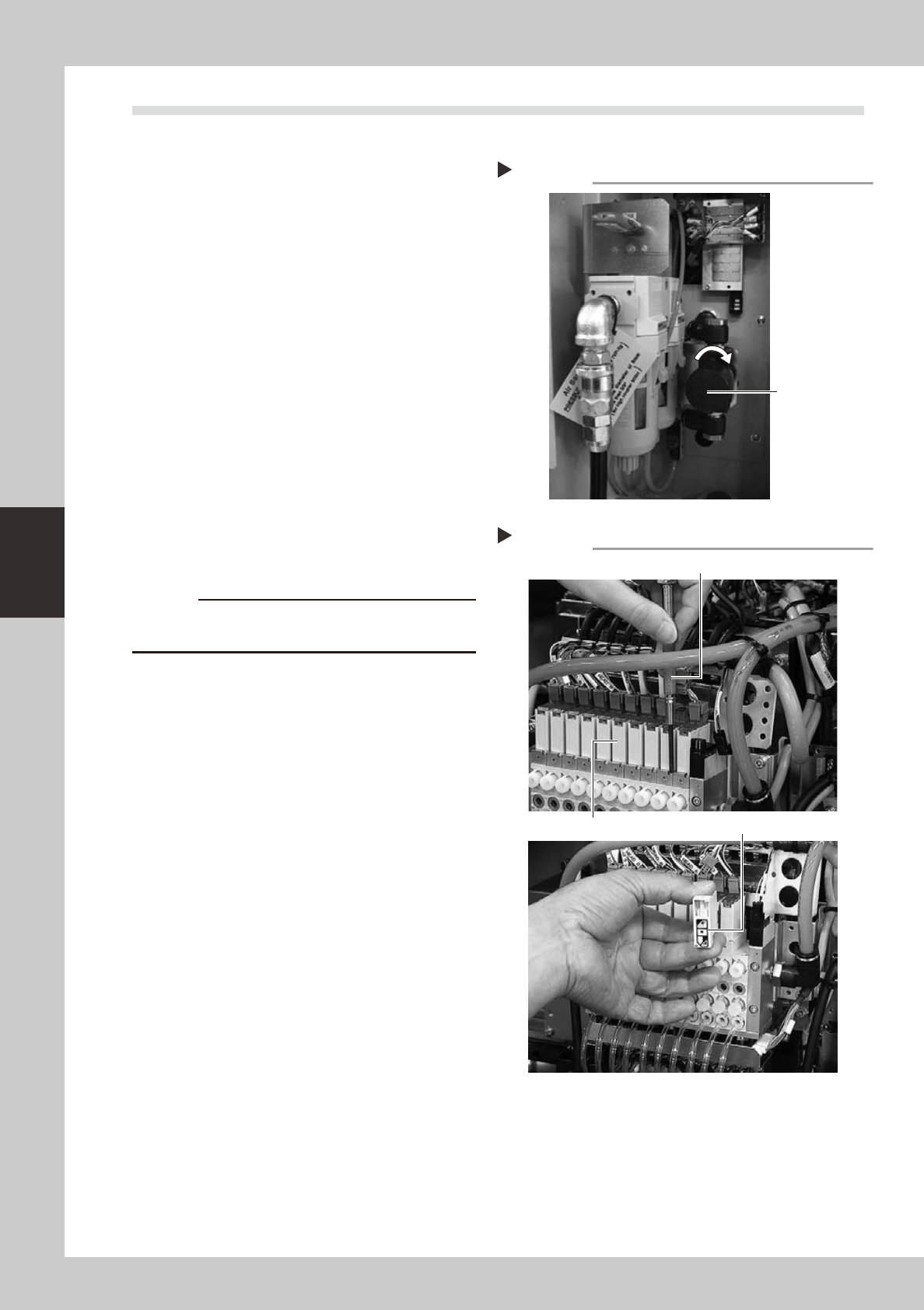
1
Turn off the air supply and the
power to the machine.
Quit the software and turn off the machine
power switch. Then turn the air supply/
shutoff valve inside the machine lower left
panel to the right, to stop the air supply.
53405-L5-00
2
Move the head to a convenient
position for replacement work.
3
Disconnect the connectors of the
ejector harness.
Disconnect all connectors of the ejector
harness.
4
Remove the solenoid coil to be
replaced.
Use a precision Phillips screwdriver to loosen
the two screws securing the solenoid coil
and then remove the solenoid coil.
53426-L5-00
5
Attach a new solenoid coil.
c
When replacing a solenoid coil, be careful not to drop
6
Reconnect the ejector harness.
Reconnect the connectors of the ejector
harness.
7
Supply air to the machine and turn
on the machine power.
When the machine has started, perform
return-to-origin.
8
Check the operation.
Generate a negative pressure (vacuum)
with the same procedure described in 3.1.2,
"Checking the blow valve operation" in
Chapter 3, and check that no abnormal
values appear.
Shutting off the air supply
Step 1
Air supply/shutoff
valve
Removing the solenoid coil
Step 4
Precision Phillips screwdriver
Solenoid coil
Gasket
4-5
4
How to replace consumable parts
3.3 Replacing the cleaning blow valve
1
Turn off the air supply and the
power to the machine.
Quit the software and turn off the machine
power switch. Then turn the air supply/
shutoff valve inside the machine lower left
panel to the right, to stop the air supply.
2
Move the head to a convenient
position for replacement work.
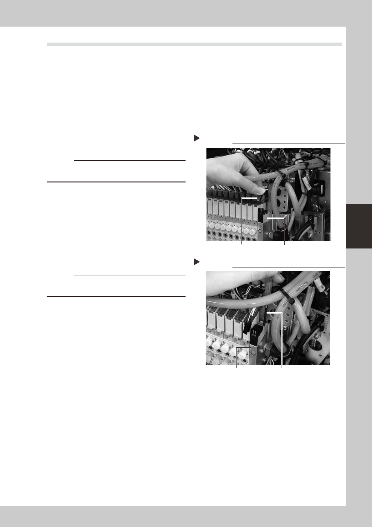
3
Disconnect the connectors of the
cleaning blow valve.
53406-L5-00
c
When disconnecting the connector, do not pull the
harness.
4
Remove the cleaning blow valve.
Use a precision Phillips screwdriver to loosen
the two screws securing the cleaning blow
valve and then remove the blow valve.
53407-L5-00
5
Attach a new cleaning blow valve
using the reverse procedure of step 4.
Also reconnect the air hoses and connectors
back to their original positions.
c
out or pinch it.
6
Supply air to the machine and turn
on the machine power.
When the machine has started, perform
return-to-origin.
7
Check the operation.
Generate a negative pressure (vacuum)
with the same procedure described in 3.1.3,
"Checking the cleaning blow valve
operation" in Chapter 3, and check that no
abnormal values appear.
Disconnecting the connector
Step 3
Blow valve connector
Blow valve
Removing the cleaning blow valve
Step 4
Precision Phillips screwdriver
Blow valve
4-6
4
How to replace consumable parts
4. Replacing a feeder valve (YG12)
1
Turn off the machine power switch.
Quit the application software (VGOS) and
turn off the machine power switch by turning
it to the left.
2
Shut off the air supply.
Open the lower left cover on the front of the
machine and turn the air supply/shutoff
switch to the right to cut off the air supply.
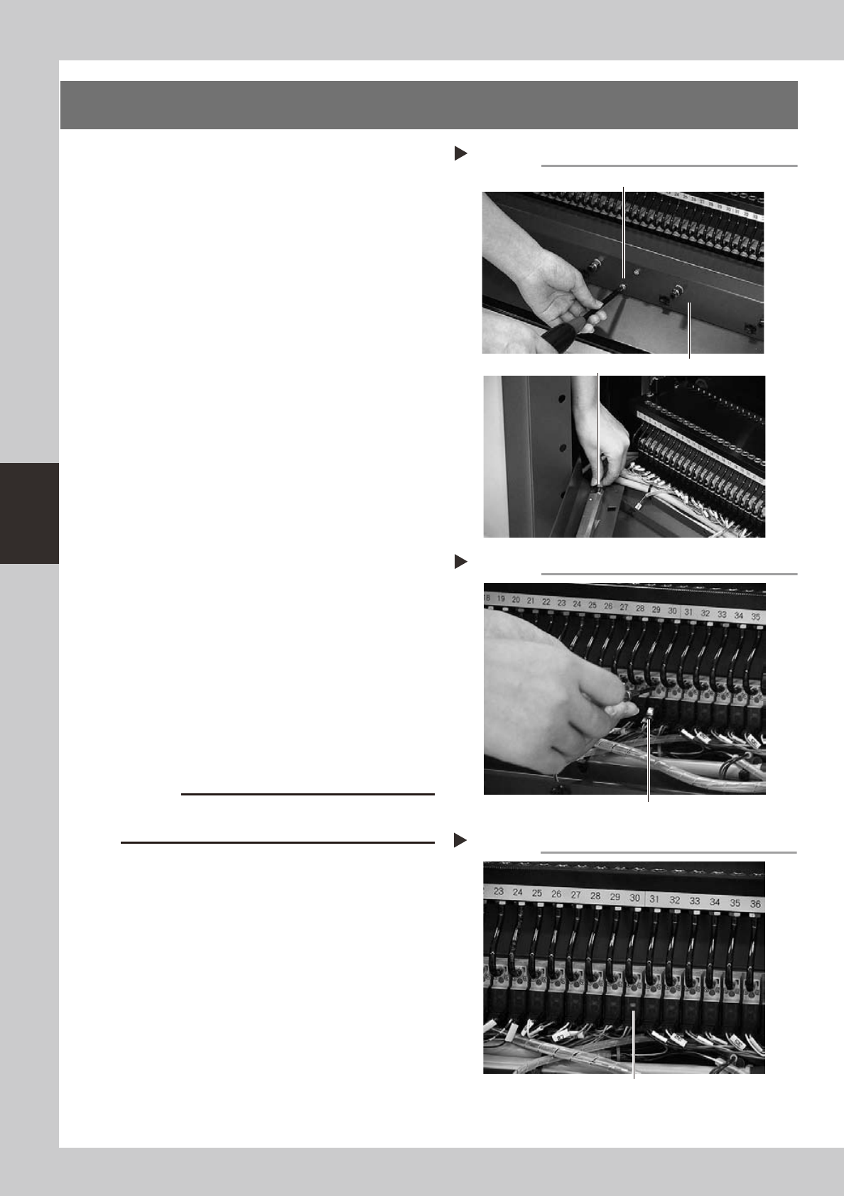
3
Remove the wire harness cover.
1. UseaPhillipsscrewdrivertoloosenand
remove the four screws that secure the
wire harness cover to the machine body.
2. Remove the air hose connected to the
wire harness cover.
53414-L5-00
4
Remove the feeder valve.
1. Detach the connector from the feeder
valve to be replaced.
2. Useaprecisionscrewdrivertoloosenthe
two screws and remove the feeder valve.
53415-L5-00
5
Remove the air hose.
Remove the air hose for the feeder valve to
be replaced. Cutting the air hose makes it
easier to remove the air hose.
(New air hoses are included in the feeder
valve kit that comes with the machine.)
6
Attach a new feeder valve and the
wire harness cover.
Install the new feeder valve and wire
harness cover in the reverse order of steps 3
and 4.
c
7
Connect an air hose.
Connect a new air hose to the new feeder
valve.
8
Check the ejector operation.
1. Supply air to the machine and turn on
the machine power switch.
2. Install a feeder at the new feeder valve
position.
3. Openthe[Unit]-[Feeder]tabscreenand
turn the feeder on and off, to check the
feeder valve and LED operations.
53416-L5-00
Removing the wire harness cover
Step 3
Wire harness cover
Remove this screw (4 places).
Air hose
Removing the feeder valve
Step 4
Valve connector
Checking the feeder valve operation
Step 8
LED lamp