YG12_英文保养手册.pdf - 第57页
3-7 3 Periodic maintenance items 2.2 Inspecting ball screws and linear guides of each axis Inspect the ball screws and the linear guides on the X, Y and W axes. Chec kpoints are listed below . A grease spattering prevent…
3-6
3
Periodic maintenance items
2. Monthly or bimonthly inspection
This section mainly explains the cleaning and lubrication procedures after inspection.
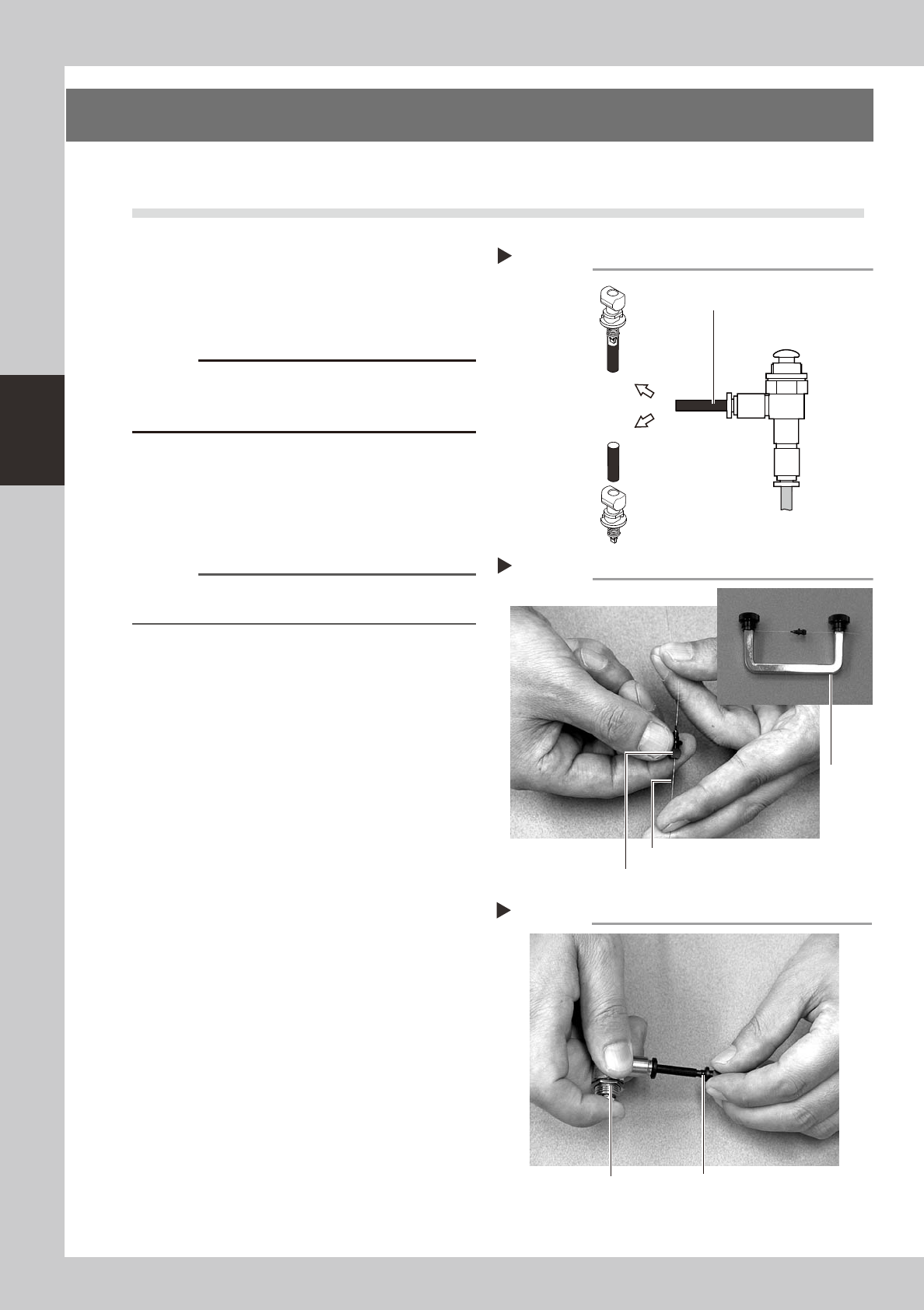
2.1 Cleaning the nozzle air path
e
1
Remove the nozzle from the head.
Always first press the emergency stop button
and then remove the nozzle from the head.
The machine must be in emergency stop to
ensure safety during work.
c
When the machine is equipped with a nozzle station
(option), make sure that the nozzles are returned to the
nozzle station after cleaning.
2
Blow air through the nozzle.
Using an air blow gun, blow air through the
nozzle from the nozzle tip and then from the
other end.
53310-L5-00
n
NOTE
If there are dust deposits in the nozzle, perform steps 3
and 4.
3
Clean the nozzle hole.
Pass the nozzle cleaning wire through the
nozzle hole and clean the nozzle hole. While
holding both ends of the wire with fingers as
shown or using a custom handle (option),
gently move the nozzle back and forth.
53311-L5-00
4
Blow air onto the nozzle tip again.
After removing the cleaning wire, blow air
through the nozzle with the air blow gun, just
as in step 2.
53312-L5-00
Following the nozzle cleaning above, check and
clean the spring-action parts. (See 1.1.1, "Checking
and cleaning the spring-action parts" described
earlier in this chapter.)
Air blow
Step 2
Air tube (black)
Air blow gun
(option)
Air tube (orange) connected to
air supply port
Insert the
nozzle tip into
the air tube and
blow air.
Blow air from the
nozzle attachment
side.
Cleaning a nozzle
Step 3
Custom
handle
(option)
Nozzle
Nozzle cleaning wire
Air blow
Step 4
NozzleAir blow gun (option)

3-7
3
Periodic maintenance items
2.2 Inspecting ball screws and linear guides of each axis
Inspect the ball screws and the linear guides on the X, Y and W axes. Checkpoints are listed below.
A grease spattering prevention cover is installed to the X and Y axes. Remove these covers when inspecting the
ball screw and linear guide.
Reference
For instructions on how to detach or attach the grease spattering prevention covers, refer to sections 2.3.1 and 2.3.2
described later on.
Checkpoints
1. Any foreign matter adhering to the ball screws and linear guides?
Check if any fallen chips have adhered to the X and Y axis ball screws and/or X, Y and W axis linear guides.
2. Do the ball screws and linear guides have the correct amount of grease?
Check if grease has flowed off or splattered in the air failing to adhere. Also check if grease has discolored or hardened.
3. Any abnormal sounds from the ball screws?
Press the emergency stop button. Then check for any abnormal sounds while pressing the head assembly or conveyor
table by hand along the X-axis or Y-axis back and forth.
Countermeasures
1. Ball screws and linear guides may be damaged when chips and other material bite into them. If chips are adhering,
wipe them off along with the grease or remove with tweezers, etc.
2. Apply grease while referring section 2.3, "Cleaning and greasing the X, Y and W axes" explained in this chapter.
3. Consult your YAMAHA sales office or representative when abnormal sounds occur even after trying the
countermeasures in the above steps 1 and 2.
3-8
3
Periodic maintenance items
2.3 Cleaning and greasing the X, Y and W axes
To clean and grease the ball screws and linear guides of the X, Y and W axes, follow the steps below. Prepare
a grease gun and specified grease (NSL).
c
When handling grease or lubricant, read and follow the precautions listed in section 2.2.2, "Lubricating tools and
grease" in Chapter 1.
c
If abnormal noise is emitted from the X, Y or W axis ball screw or linear guide, then contact our sales representative for
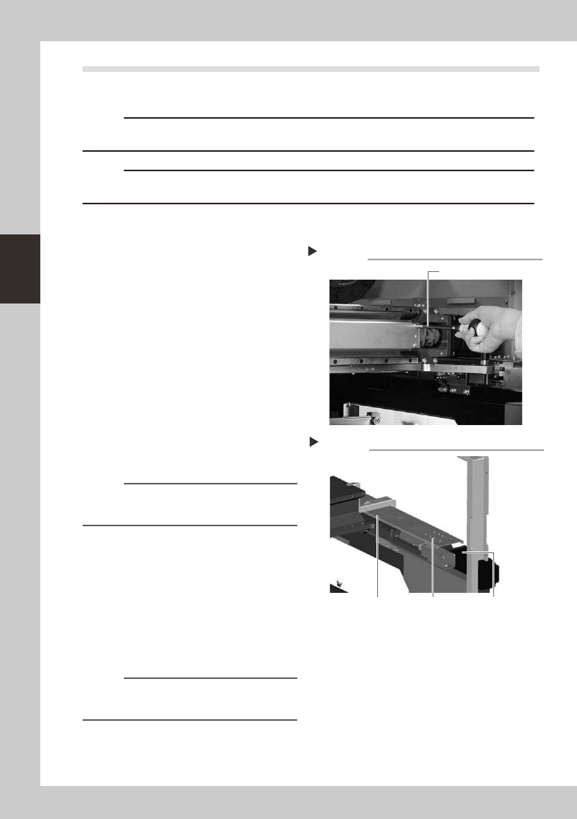
2.3.1 Cleaning and greasing the X, Y and W axis ball screws
e
1
Press the emergency stop button.
The machine must be in emergency stop to
ensure safety during work.
2
Remove the ball screw covers.
Remove the X-axis and Y-axis ball screw
covers used for preventing grease
spattering.
X-axis
1. UseaPhillipsscrewdrivertoremovethe
screws securing the left side of the
grease spattering prevention cover.
2. Move the head all the way to the left
side and remove the screws securing the
right side of the grease spattering
prevention cover.
3. Remove the grease spattering prevention
cover by pulling it to the right.
53305-L5-00
Reference
When reattaching the X-axis grease spattering
prevention cover, use the reverse order of the above
procedure.
Y1 and Y2 axes
1. Usethehexwrenchtoremovethescrews
securing the rear side of the grease
spattering prevention cover.
2. Move the head all the way to the rear
side and remove the screws securing the
front side of the grease spattering
prevention cover.
3. Remove the grease spattering prevention
cover by pulling it to the front.
53306-L5-00
Reference
When reattaching the Y-axis grease spattering
prevention covers, use the reverse order of the above
procedure.
Removing the X-axis grease spattering prevention cover
Step 2
Phillips screwdriver
Y-axis ball screw cover
Step 2
Y-axis ball screw
cover mounting bolt
Y-axis motor
Removing the Y-axis grease spattering prevention cover