YG12_英文保养手册.pdf - 第94页
4-9 4 How to replace consumable parts 6. Lubrication points This section describes lubrication points, inter vals and procedures. n Grease Use the following specified grease. Grease name : NSL P art No. : K48-M3856-00X 6…
4-8
4
How to replace consumable parts
5
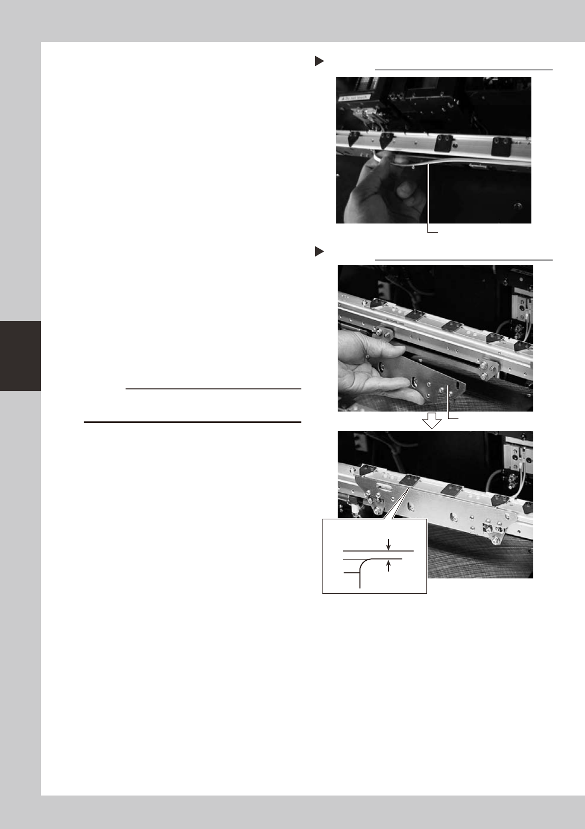
Detach the belt from the conveyor.
53421-L5-00
6
Clean the conveyor rail.
Use a fine brush or cleaning cloth to clean
the gap between the conveyor rail and
board guide.
7
Attach a new belt.
1. Temporarily fit a new belt onto the pulley.
2. Reconnect the shaft to the pulley and
tighten the bolt.
3. Tighten the belt tensioner bolt while
applying a proper tension to the belt by
moving the belt tensioner bolt.
8
Reattach the board clamp assembly.
1. Install the board clamp assembly in the
original position and temporarily tighten
the bolts to secure the board clamp
assembly.
2. Onthe[Unit]–[Conveyor]tab,pressthe
[Board Clamp] button to raise the board
clamp assembly and tighten the bolts
securely.
53422-L5-00
c
and the board clamp raised.
9
Check the belt rotating condition.
1. Openthe[Unit]-[Conveyor]tab,and
press the [Board Clamp] button again to
unclamp. At this point, make sure that
the top of the board clamp assembly is
0.5mm lower than the upper surface of
the belt.
2. Onthe[Unit]-[Conveyor]tab,pressthe
[Conveyor In] button or [Conveyor Out]
button to turn on the conveyor motor
and check the belt rotation.
3. If the rotation speed fluctuates or there is
slack in the belt, adjust the position of
the tensioner bolt and then check the
rotation again.
Step 5
Detaching the belt from the conveyor
Pull out the belt.
Installing the board clamp assembly
Step 8
Board clamp assembly
0.5 mm
Board clamp
Belt upper surface
4-9
4
How to replace consumable parts
6. Lubrication points
This section describes lubrication points, intervals and procedures.
n
Grease
Use the following specified grease.
Grease name : NSL
Part No. : K48-M3856-00X
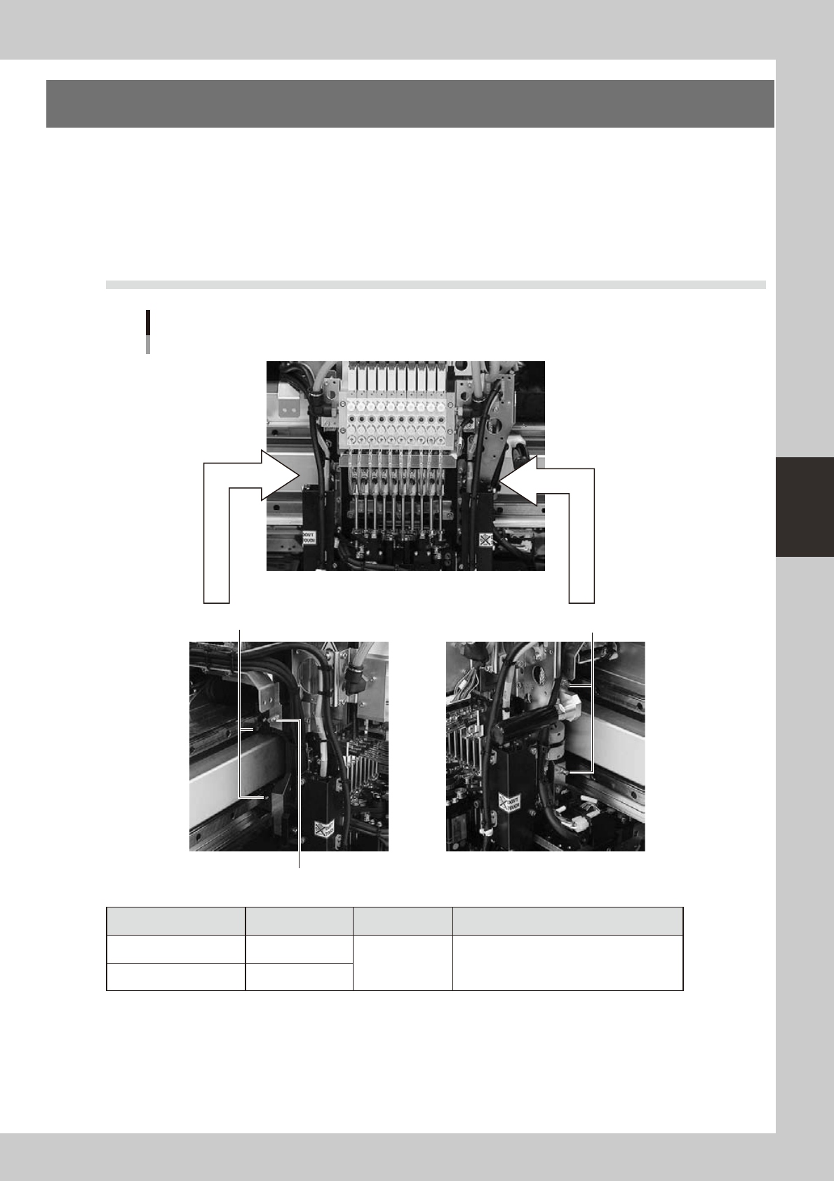
6.1 X-axis linear guide and ball screw
X-axis linear guide
X-axis lubrication points
Grease nipples (small) 2 places
Grease nipples (large) 2 places
X-axis ball screw
Grease nipples (large) 1 place
Lubrication section Lubrication point Interval Procedure
Linear guide 4
Once a month Grease gun
Ball screw 1
53435-L5-00
4-10
4
How to replace consumable parts
6.2 Y1 and Y2 axis linear guide and ball screw
Y-axis lubrication points
Grease nipple for Y-axis ball screw
Y2 axis (left side) Y1 axis (right side)
Grease nipples (2 places each on front and rear)
for Y-axis linear guide
Grease nipples (2 places each on front and rear)
for Y-axis linear guide
Grease nipple for Y-axis ball screw
Lubrication section Lubrication point Interval Procedure
Linear guide 4
Once a month Grease gun
Ball screw 2
53436-L5-00
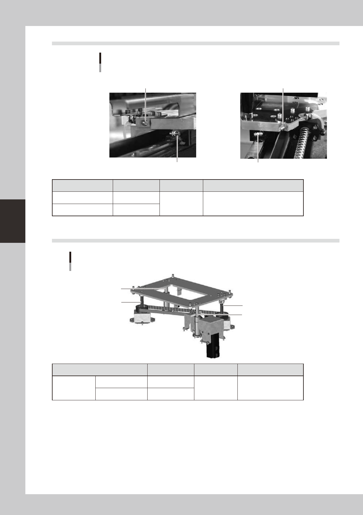
6.3 PU-axis linear guide and ball screw
PU-axis lubrication points
Ball screw
Ball screw
Ball guide
Ball guide
Lubrication section Lubrication point Interval Procedure
Single PU
Ball guide 2
Once a month Apply grease by hand.
Ball screw 2
53437-L5-00