YG12_英文保养手册.pdf - 第81页
3-31 3 Periodic maintenance items 4.5 Inspecting and cleaning the controller filter (1 year) A fan is installed on the lower part of the controller to cool the circuit boards inside the controller . T urning on the main …
3-30
3
Periodic maintenance items
4.4 Checking the nozzle station sensor condition (1 year) … option
When the machine is equipped with a nozzle station (option), check the nozzle station sensors to see if they
are working correctly.
c
If a nozzle station sensor fails to detect a nozzle, the nozzle change cannot be performed correctly and the machine
operation may be interrupted due to a nozzle detection error.
e
1
Press the emergency stop button.
The machine should be in emergency stop
to ensure safety during work.
2
Open the nozzle station shutter.
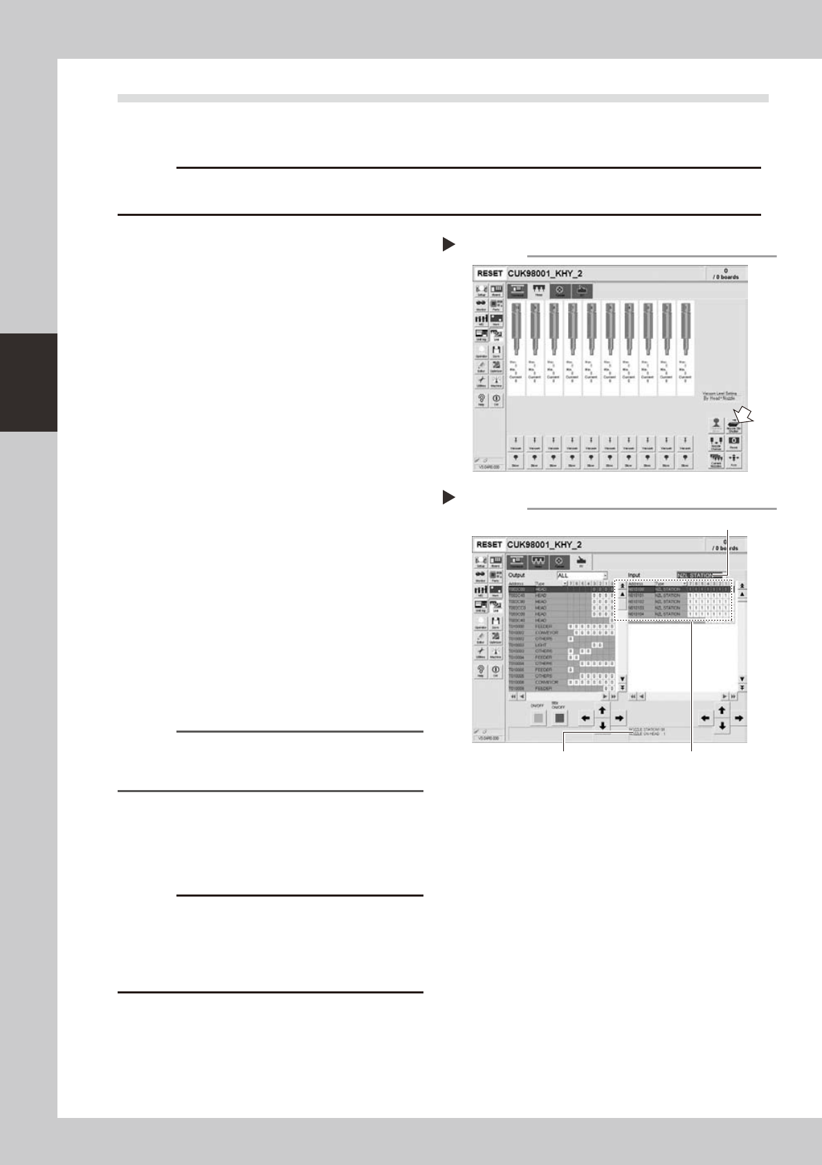
1. Openthe[Unit]-[Head]tab.
2. Press the [Nozzle Stn Shutter] button to
open the nozzle station shutter.
54303-L5-00
3
Check the detection status of the
nozzle station sensors.
Check to see if the nozzle station sensors
detect the presence or absence of nozzles.
1. Openthe[Unit]-[I/O]tab.
2. From the "Input" drop-down list, select
"NZL STATION".
3. While extracting a nozzle from the nozzle
station and returning it to the same
position, check whether the
corresponding sensor detects the nozzle
correctly.
The detection status on the screen should
read "1" when the nozzle is extracted
from the nozzle station, and should read
"0" when the nozzle is in the nozzle
station.
54306-L5-00
Reference
The nozzle station position No. where a nozzle was
extracted or inserted is displayed on the lower part of
the "Input" status screen.
4
Close the nozzle station shutter.
On the [Unit]-[Head] tab, press the [Nozzle
Stn Shutter] button to close the nozzle station
shutter.
c
If the detection status of a nozzle station sensor is
unstable or a senor fails to detect a nozzle, then contact
and cleaning of the nozzle station sensors by the user
will void the warranty.
Opening the shutter
Step 2
Checking the nozzle detection status
Step 3
Select "NZL STATION".
Nozzle station position No. is
displayed here.
Shows the presence or absence
of nozzles detected by sensors.
3-31
3
Periodic maintenance items
4.5 Inspecting and cleaning the controller filter (1 year)
A fan is installed on the lower part of the controller to cool the circuit boards inside the controller. Turning on
the main power starts a continual supply of air. The filter removes dust from the air taken in through the fan.
Accumulated dust may cause faulty operation, so clean the filter periodically.
1
Turn off the air supply and the
power to the machine.
Quit the software and turn off the machine
power switch. Then turn the air supply/
shutoff valve inside the machine lower left
panel to the right.
2
Open the air release valve inside
the tape cutter.
Discharge any remaining air that is
accumulated inside the tape cutter.
c
To remove the tape cutter duct, any air remaining in the
tape cutter must be discharged to free the tape cutter
blade.
3
Remove the front tape cutter ducts.
Use a Phillips screwdriver to remove the
screws securing the left and right tape cutter
ducts, and remove the ducts. (Remove a
total of 6 screws.)
c
Removing the tape cutter ducts exposes the tape cutter
blade. Coming in contact with the blade may cause
cuts and injuries, so be careful not to touch the blade.
4
Remove the front lower panel to
access to the controller.
Remove the front panel under the machine
front base, where the controller is installed.
5
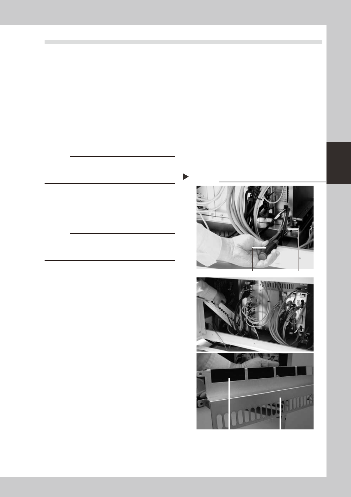
Remove the filter.
Use a Phillips screwdriver to remove the
screws on the left and right of the filter
frame, and remove the filter along with the
filter frame.
53350-L5-00
6
Clean or replace the filter.
The filter is attached to the filter frame.
Check for dirt and clean by air blow. If the
dirt is too tough to remove, then replace the
filter.
7
Reinstall the filter.
Reinstall the filter back to its original position.
Reinstall the front panel and the tape cutter
ducts.
8
Close the air release valve inside
the tape cutter.
9
Turn on the machine power and
start the air supply.
Turn on the machine power switch and also
start the air supply by turning the air supply/
shutoff valve inside the machine lower left
panel to the left.
Removing the filter
Step 5
Phillips screwdriver
Screw (1 each on left and right)
Filter coverFilter is attached to filter frame.
3-32
3
Periodic maintenance items
4.6
Cleaning the multi-view camera lens and lighting unit (1 year) …. option
The multi-view camera lens and lighting unit are enclosed inside the transparent cover. To clean the lens and
lighting unit, remove the transparent cover. If the transparent cover is dirty, clean it (see section 5, "Cleaning
the camera transparent cover", in Chapter 2).
1
Turn off the power to the machine.
Quit the software and turn off the machine
power switch.
2
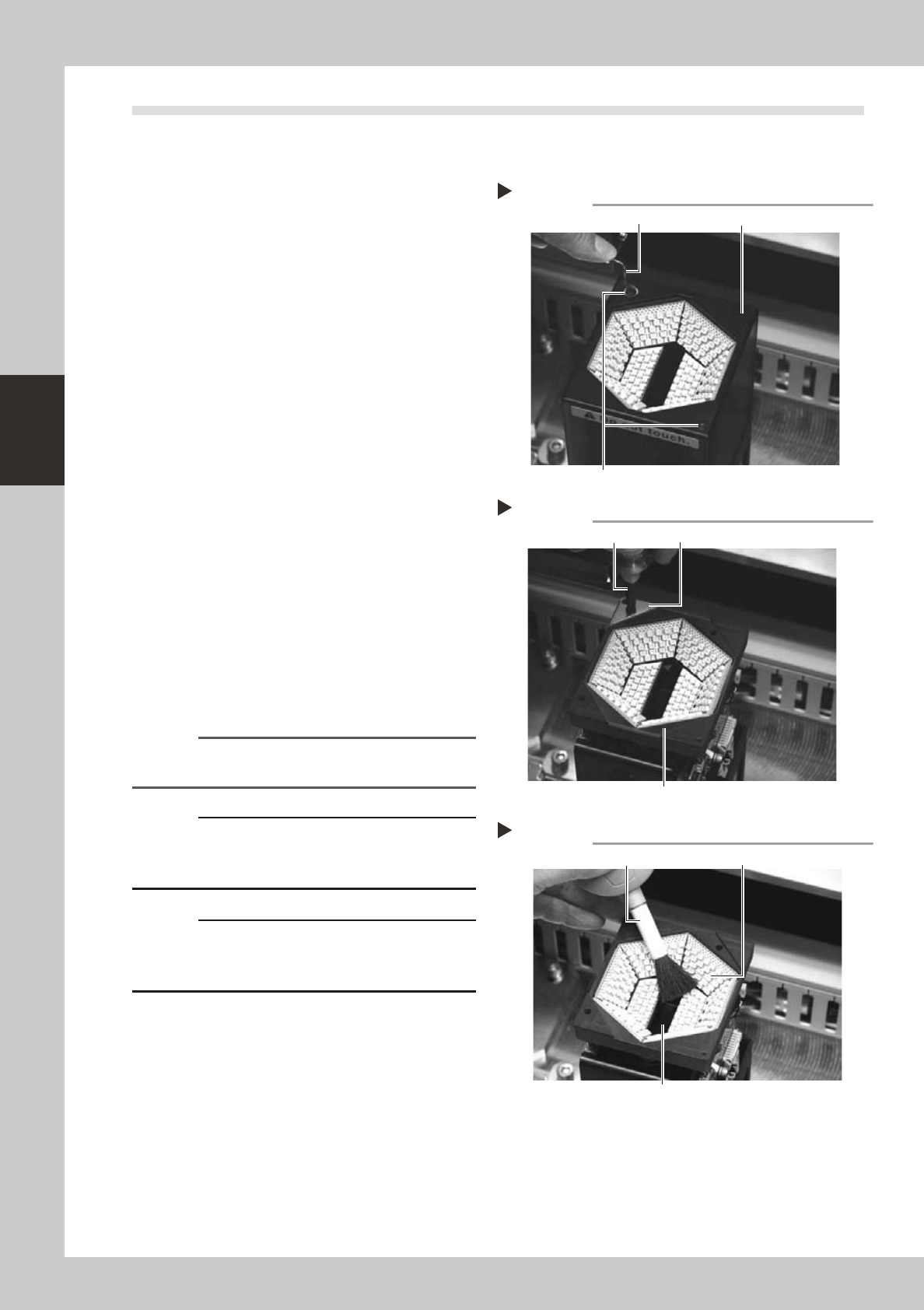
Remove the upper cover of the
multi-view camera.
Use a hex wrench to remove the two
thin-head screws on the upper cover of the
multi-view camera. Then carefully lift the
multi-view camera cover straight up and
remove it.
53341-L5-00
3
Remove the transparent protective
glass.
Use a Phillips screwdriver to remove the
screws securing the glass mount plate.
53342-L5-00
4
Clean the lighting unit.
1. Many LEDs are mounted on the lighting
board.Usealensbrushtocleanthe
LEDs.
2. A half mirror is located in the center
opening of the lighting unit. Clean the
half mirror using a lens brush, lint-free
cotton swab, lens cleaner, etc.
53343-L5-00
Reference
Lens brush, lint-free cotton swab, and lens cleaner are
available as options.
c
or may cause short-circuits.
c
The half mirror is very thin with a thickness of 1.0mm.
Even a small shock can cause cracks. Use extreme
caution when cleaning the half mirror.
Removing the multi-view camera cover
Step 2
Hex wrench
Thin-head screw
Multi-view camera cover
Removing the protective glass
Step 3
Phillips screwdriver
Protective glass
Glass mount plate
Cleaning the multi-view camera lighting unit
Step 4
Lens brush
Half mirror glass
LED