YG12_英文保养手册.pdf - 第87页
4-2 4 How to replace consumable parts 2. Replacing an air joint (YG12) e 1 Pr ess the emer gency stop button. The machine must be in emergency stop to ensure safety during work. 2 Remo ve the defective air joint. Insert …
4-1
4
How to replace consumable parts
1. Replacing nozzle leaf springs
e
1
Press the emergency stop button.
The machine must be in emergency stop to
ensure safety during work.
2
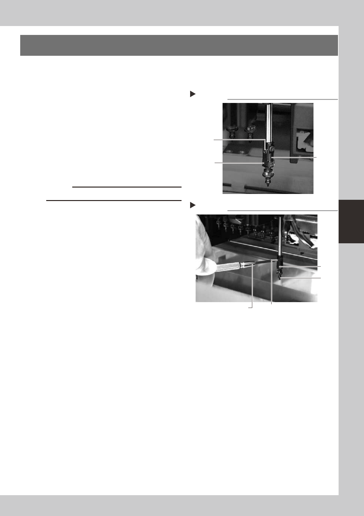
Remove the nozzle.
Remove the nozzle attached to the leaf
springs to be replaced, by pulling it
downwards by hand.
3
Remove the leaf springs.
Use a Phillips precision screwdriver to loosen
the screws securing the defective leaf
springs and remove the leaf springs from the
nozzle holder while pressing the nozzle shaft
from the back.
53400-L5-00
c
4
Attach new leaf springs.
While pressing the nozzle shaft from the
back, tighten the screw with the Phillips
precision screwdriver to assemble the leaf
spring.
53401-L5-00
5
Reattach the nozzle.
6
Check that the nozzle is held
securely.
1. Check that there is no gap between the
leaf springs and nozzle.
2. Attempt detaching and attaching the
nozzle several times to check that there
is no looseness.
Removing nozzle leaf springs
Step 3
Nozzle leaf
spring mounting
screw
Nozzle
holder
Nozzle leaf
spring
Attaching nozzle leaf springs
Step 4
Leaf
spring
Nozzle
Nozzle leaf spring mounting screw
Precision screwdriver
4-2
4
How to replace consumable parts
2. Replacing an air joint (YG12)
e
1
Press the emergency stop button.
The machine must be in emergency stop to
ensure safety during work.
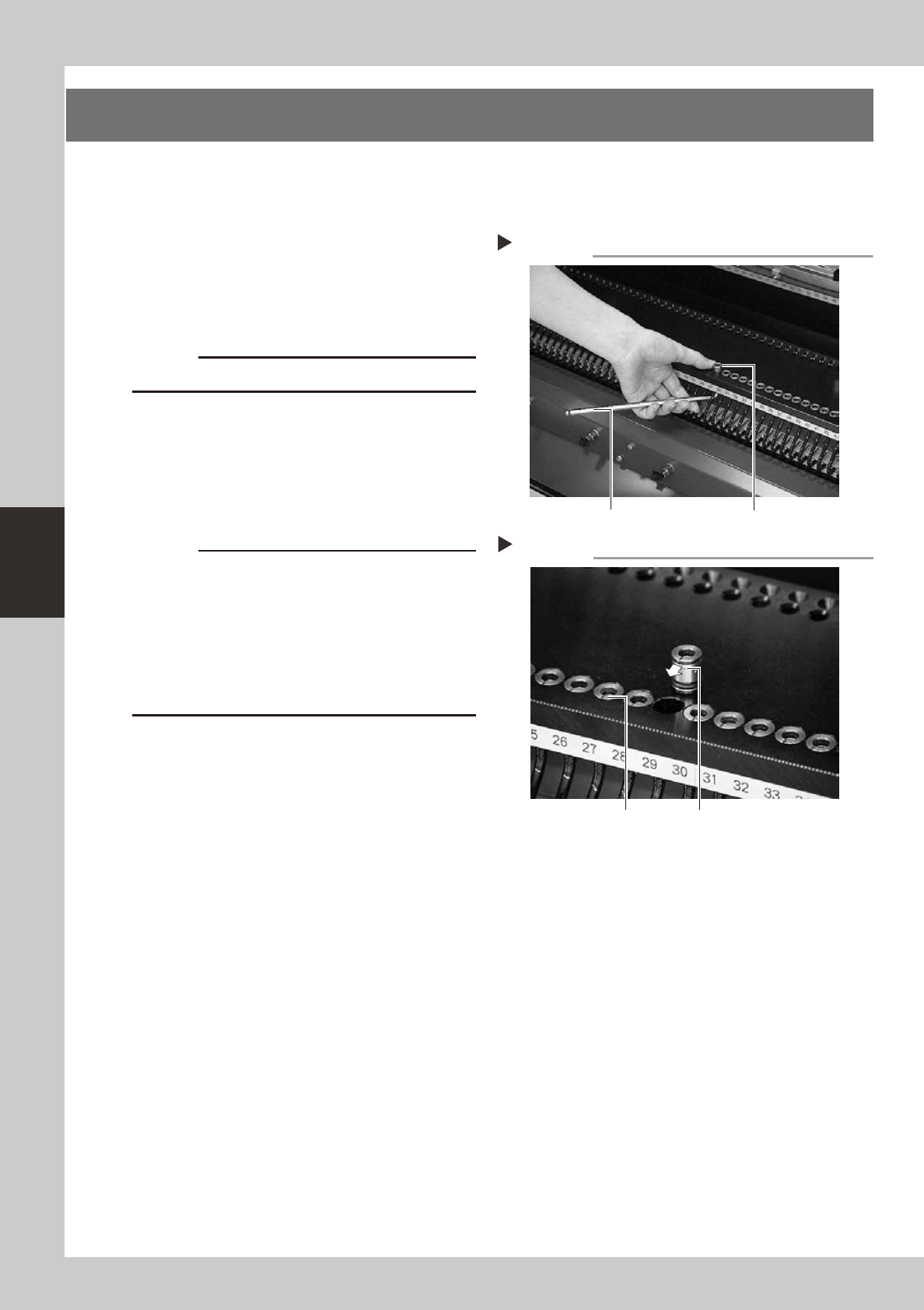
2
Remove the defective air joint.
Insert an M8 hex wrench at the bottom of
the air joint and push it up, then take the air
joint out.
53403-L5-00
c
Be careful not to damage the air hoses.
3
Install a new air joint.
While holding the air joint so the mark
(notch) faces the front side of the machine,
insert it into position from the top of the
feeder plate.
53404-L5-00
c
of the machine. If the air joint is inserted without
aligning the mark orientation, dust or debris may
penetrate into the air hose.
surface is lower than the feeder plate surface. Air
joints will slightly rise over time. Reinsert them into
position.
4
Check the operation.
1. Install a feeder at the new air joint
position.
2. Openthe[Unit]-[Feeder]tabandcheck
the feeder on/off operation.
Removing the air joint
Step 2
Air joint
Hex wrench
Installing an air joint
Step 3
Mark orientation
Concave mark
4-3
4
How to replace consumable parts
3. Ejector unit
3.1 Replacing an ejector bit
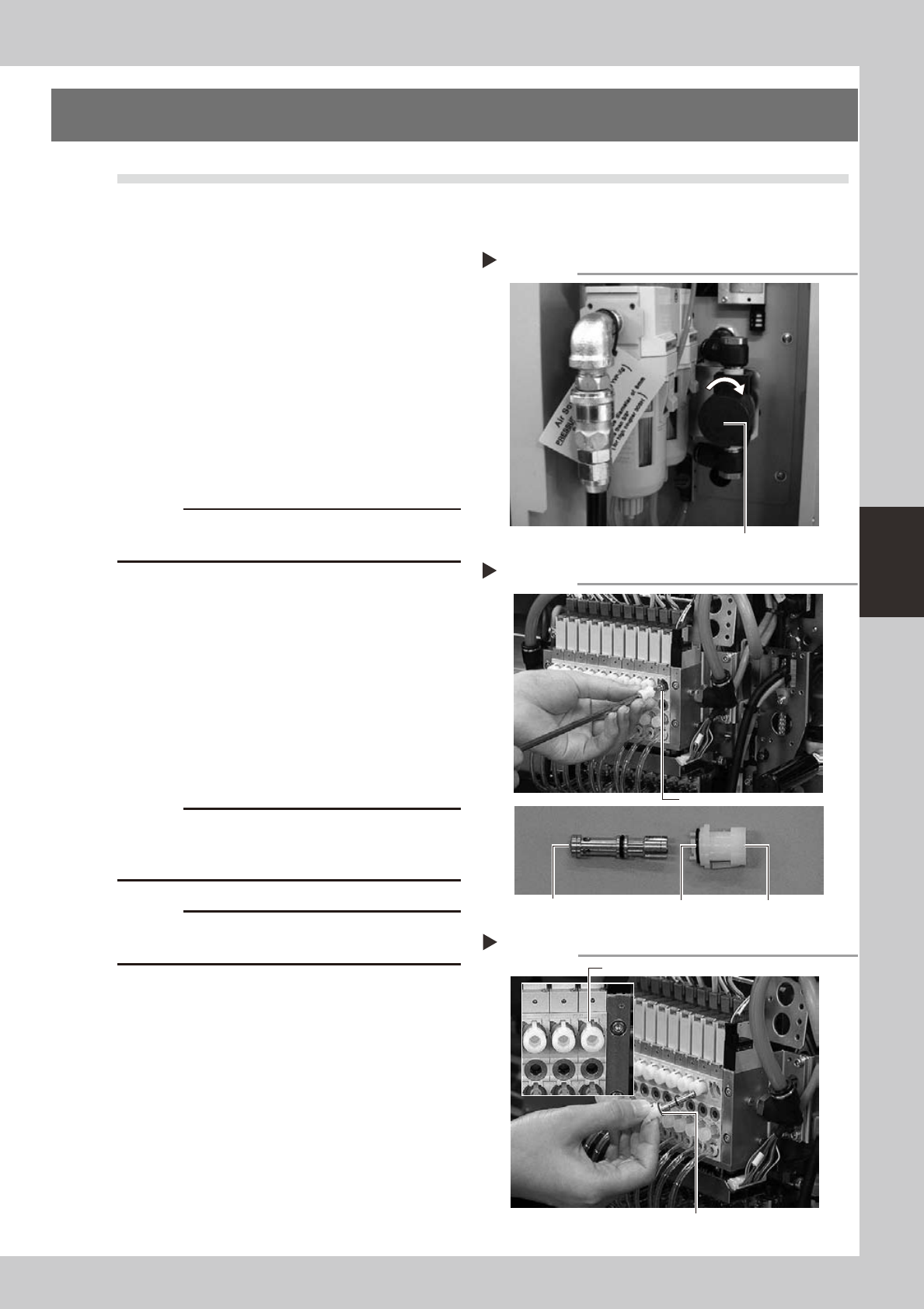
1
Shut off the air supply.
Turn the air supply/shutoff valve inside the
machine lower left panel to the right, to stop
the air supply.
53346-L5-00
2
Move the head to a convenient
position for replacement work.
3
Pull out the ejector bit by hand.
Remove the cap by turning it to the left with
a hex wrench. The end of the bit is seen
sticking out of the ejector unit. Pull out the
bit by hand.
53424-L5-00
c
The removed bit cannot be reused. Reuse may cause
component pickup errors.
4
Clean the bit installation hole.
Remove dust or grime in the installation hole
using an air blow gun (available as an
option), lint-free cotton swab, etc.
5
Install a new bit.
Fit an O-ring to the new bit and install one
end of the bit into the cap. Then insert the
bit into the installation hole and close the
cap by turning it to the right.
53425-L5-00
c
If the bit is not installed in place, it may fly out when
vacuum is turned on. Always make sure that the bit is
securely installed.
c
When closing the cap after inserting the bit, be careful
6
Supply air to the machine.
Turn the air supply/shutoff valve inside the
machine lower left panel to the left, to start
the air supply.
Shutting off the air supply
Step 1
Air supply/shutoff valve
Removing the bit
O-ring CapBit
Step 3
Bit installation hole
Installing the bit
O-ring
Not installed in place
Step 5