YG12_英文保养手册.pdf - 第62页
3-12 3 Periodic maintenance items 3 Apply new grease to the guide r ails. 1. X axis Usethegreaseguntosupplythe specified grease (NSL) to the X-axis linear guide grease nipples. The grease nipples are located behin…
3-11
3
Periodic maintenance items
2.3.2 Cleaning and greasing the X, Y and W axes linear guides
e
1
Press the emergency stop button.
The machine must be in emergency stop to
ensure safety during work.
2
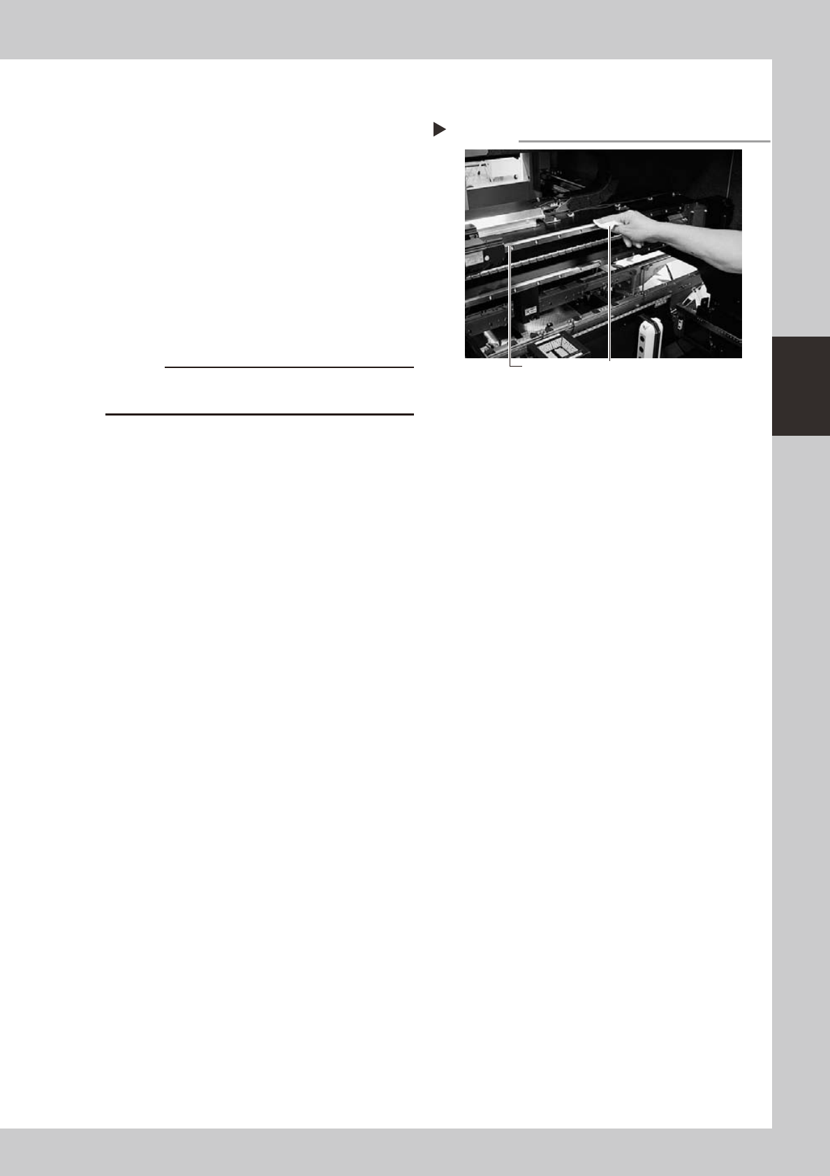
Clean the linear guides.
1. Move the head (or conveyor rails) to one
end of its axis, and wipe away the old
grease and dirt from the linear guides
with a lint-free cloth or paper towel.
2. Move the head (or conveyor rails) to the
opposite side of its axis and wipe the
linear guides. (X, Y and W axes)
53313-L5-00
c
Wipe away thoroughly the old grease in the grooves of
the linear guide rails.
Cleaning the linear guides
Step 2
Guide rail Wipe with cleaning cloth or paper towel.
3-12
3
Periodic maintenance items
3
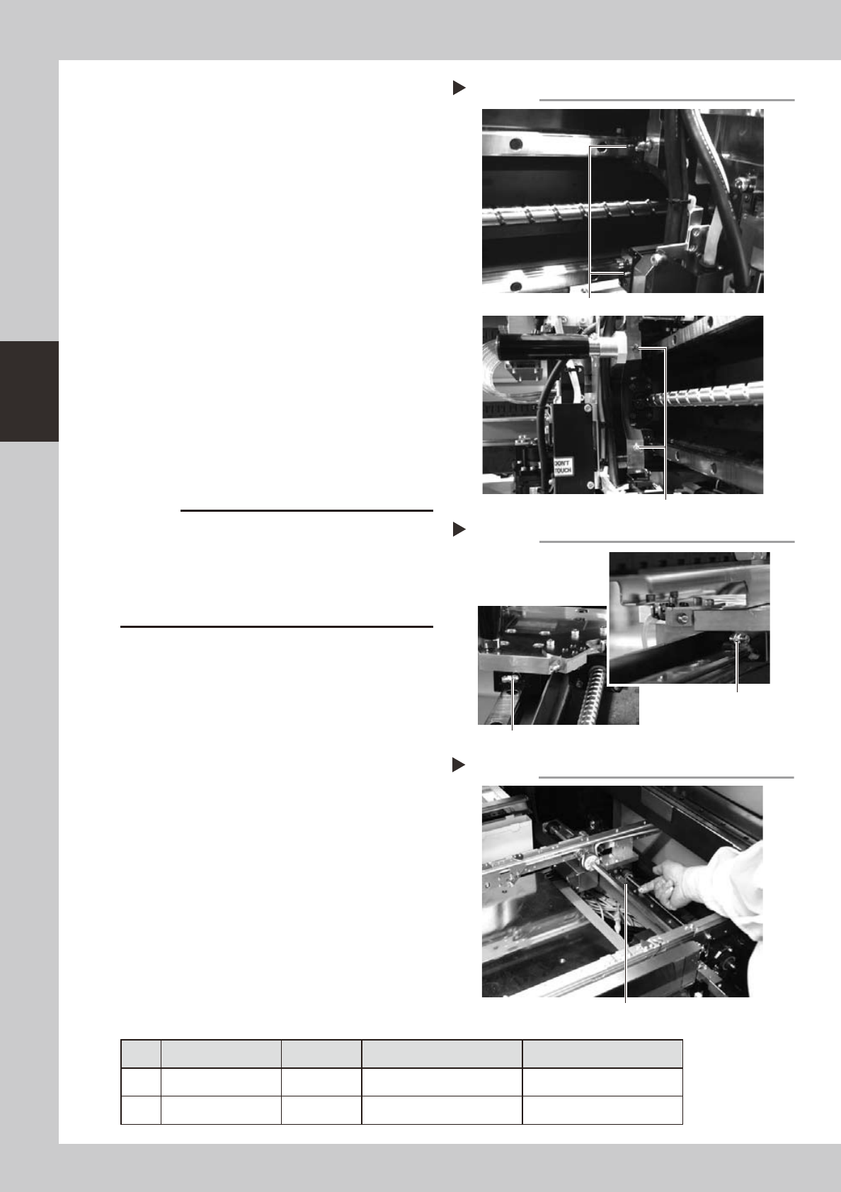
Apply new grease to the guide rails.
1. X axis
Usethegreaseguntosupplythe
specified grease (NSL) to the X-axis linear
guide grease nipples.
The grease nipples are located behind
the head assembly, two each on the
right and left at the positions (heights) of
the upper and lower linear guides (total
of 4 places).
53314-L5-00
2. Y1 and Y2 axes
Usethegreaseguntosupplythe
specified grease (NSL) to the Y-axis linear
guide grease nipples. The grease nipples
are located on the front and back sides
of the slider on each Y-axis linear guide
(total of 4 places).
Attach the grease gun nozzle to the
grease gun so that the grease gun nozzle
can be aligned with the angle of the
grease nipples.
53329-L5-00
c
When injecting grease from the bent type grease
nipples on the front and back sides of the Y-axis, align
the grease gun nozzle with the angle of the grease
nipple. If not aligned, the grease nipple may be
damaged or may come loose and fall off. Carefully
align the grease gun with the grease nipple.
3. W axis
Apply grease (NSL) by hand uniformly
over the surface and groove of the linear
guide rails.
53330-L5-00
4
Remove excess grease.
After moving the head (or conveyor rails)
back and forth a few times along their axes,
wipe away excess grease.
n
Grease list
For linear guides
No. Axis Grease name Grease type How to grease
1 X and Y axes NSL Lithium-based grease Use a grease gun.
2 W axis NSL Lithium-based grease Apply grease by hand.
Greasing the X-axis linear guide
Step 3-1
Grease nipple (small)
Grease nipple (large: located on head holder)
Greasing the Y-axis linear guide
Step 3-2
Grease nipple for
Y-axis linear guide
Grease nipple for Y-axis linear guide Total of 4 places
Greasing the W-axis linear guide
Step 3-3
W-axis linear guide
3-13
3
Periodic maintenance items
2.4 Inspecting, cleaning and greasing the push-up shaft
The push-up shaft is designed to prevent flexing or warping of the board during clamping and is important
because it prevents depressing of the board during component mounting.
The push-up shaft also prevents deviations in the component mounting accuracy due to the board depressing
during component mounting, so it is important to regularly clean and inspect the push-up shaft to ensure it
operates correctly.
c
cleaning of the push-up shaft by the user will void the warranty.
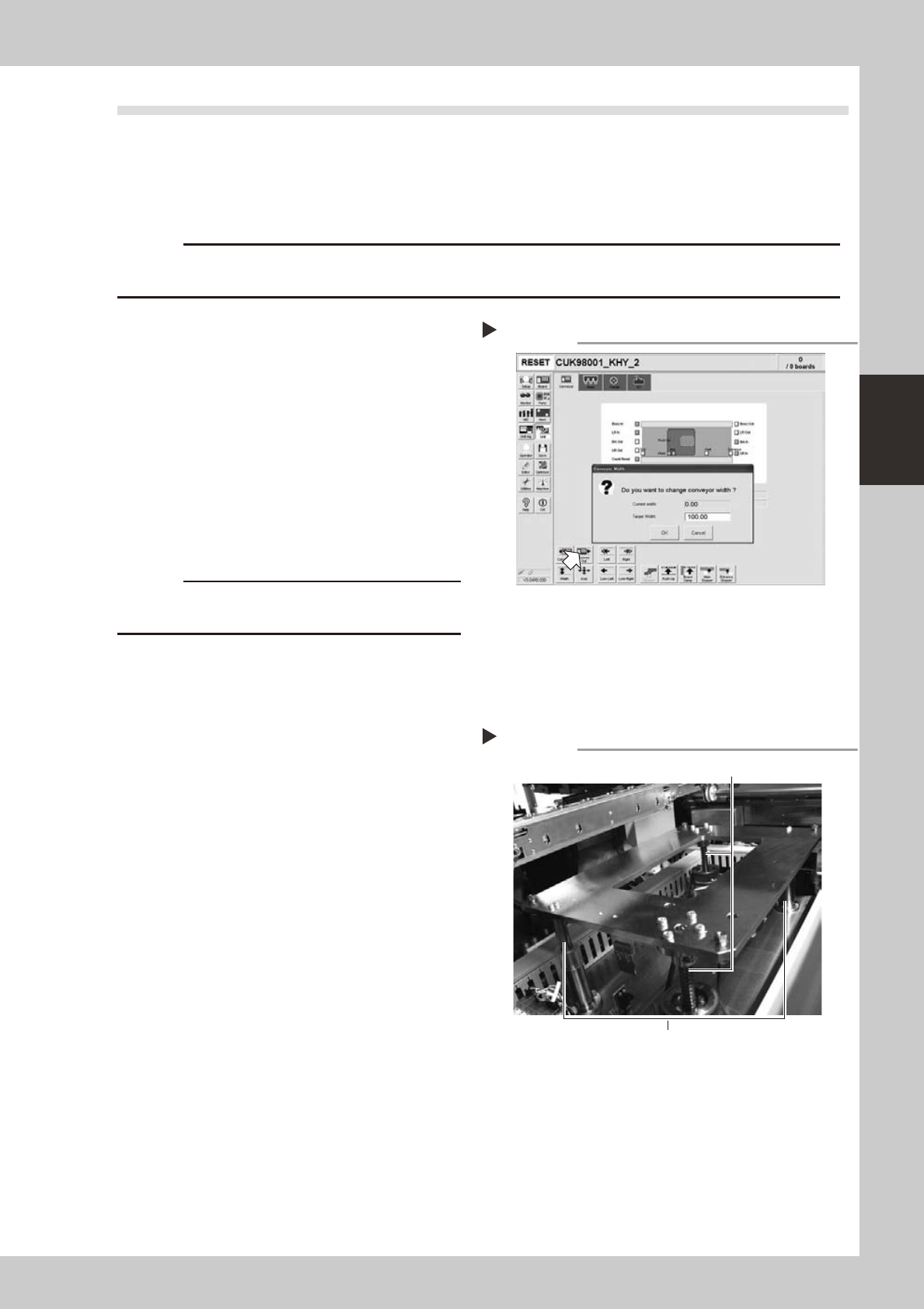
1
Set the conveyor width to
maximum.
Press the [Width] button to display the
"Conveyor Width" dialog. Enter the maximum
conveyor width from the specifications and
press [OK]. The conveyor is changed to the
width that was just entered.
54310-L5-00
e
2
Remove the push-up plate.
Press the emergency stop button and then
remove the push-up plate using a hex
wrench.
c
The push-up plate is heavy so use plenty of caution
during handling.
3
Raise the push-up unit.
Cancel emergency stop and raise the
push-up unit manually.
e
4
Remove the old grease by hand.
After pressing the emergency stop button,
thoroughly remove the old grease from the
two ball screws and the two ball guides by
hand.
5
Apply the new grease by hand.
Ball screw
Apply as much as 2 cm of new grease to
your finger, and rub it evenly into the ball
screw grooves.
Ball guide
Apply as much as 2 cm of new grease to
your finger, and coat it evenly on the ball
guides.
53331-L5-00
Setting the conveyor width
Step 1
Applying the grease
Step 5
Ball guides (2 places)
RU-axis ball guides (2 places)