YG12_英文保养手册.pdf - 第99页
A-2 Appendix 1.2 Power connection terminals T he power connection terminals are located inside the lower right panel on the front of the mac hine. Connect the power cable leads as shown belo w to the L1, L2, L3 and groun…
A-1
Appendix
1. Specifications
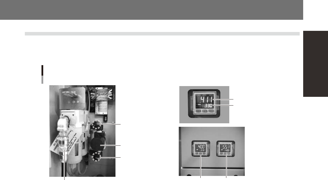
1.1 Air regulator unit
The air regulator for controlling the air pressure to the pneumatic units of the machine is located behind the
front lower left panel. A digital pressure gauge is provided on the front left of the machine. The air pressure
must be set to the optimum level.
Air pressure regulator
for machine
Air pressure regulator
for head (YG12)
Air supply/shutoff
switch (valve)
Source air connector
Air pressure regulator and pressure gauge
Air pressure setting
for machine
Pressure-drop
detection level
Air pressure setting for machineAir pressure setting for head
YS12
YG12
53427-L5-00
■
Supply air pressure
This is the pressure of the source air supplied to the machine. Before setting the air pressure with the air regulator, make
sure that this supply air pressure is in the following optimal range.
YS12 : 0.45MPa to 0.70MPa
YG12 : 0.60MPa to 0.70MPa
■
Digital pressure gauge
Shows the supply air pressure (upper reading) and pressure-drop detection level (lower reading). A normal pressure value
is shown in green, and a pressure value lower than the pressure-drop detection level is shown in red.
■
Air pressure setting and pressure-drop detection level
• YS12
Air pressure setting for machine (upper reading) : 0.40MPa
Pressure-drop detection level (lower reading) : 0.33MPa
• YG12
Air pressure setting for machine (upper reading on right pressure gauge) : 0.55MPa
Pressure-drop detection level (lower reading on right pressure gauge) : 0.40MPa
Air pressure setting for head (upper reading on left pressure gauge) : 0.40MPa to 0.41MPa
Pressure-drop detection level (lower reading on left pressure gauge) : 0.33MPa
■
Air supply/shutoff switch (valve)
Turning this switch to the right shuts off air supply and exhausts air that remains inside the machine.
■
Source air connector
Prepare an air hose with an inner diameter of at least 8mm having a 40SH socket (Nitto Koki, or equivalent), and connect
it to this connector. Use dry, clean air passed through an air filter.
A-2
Appendix
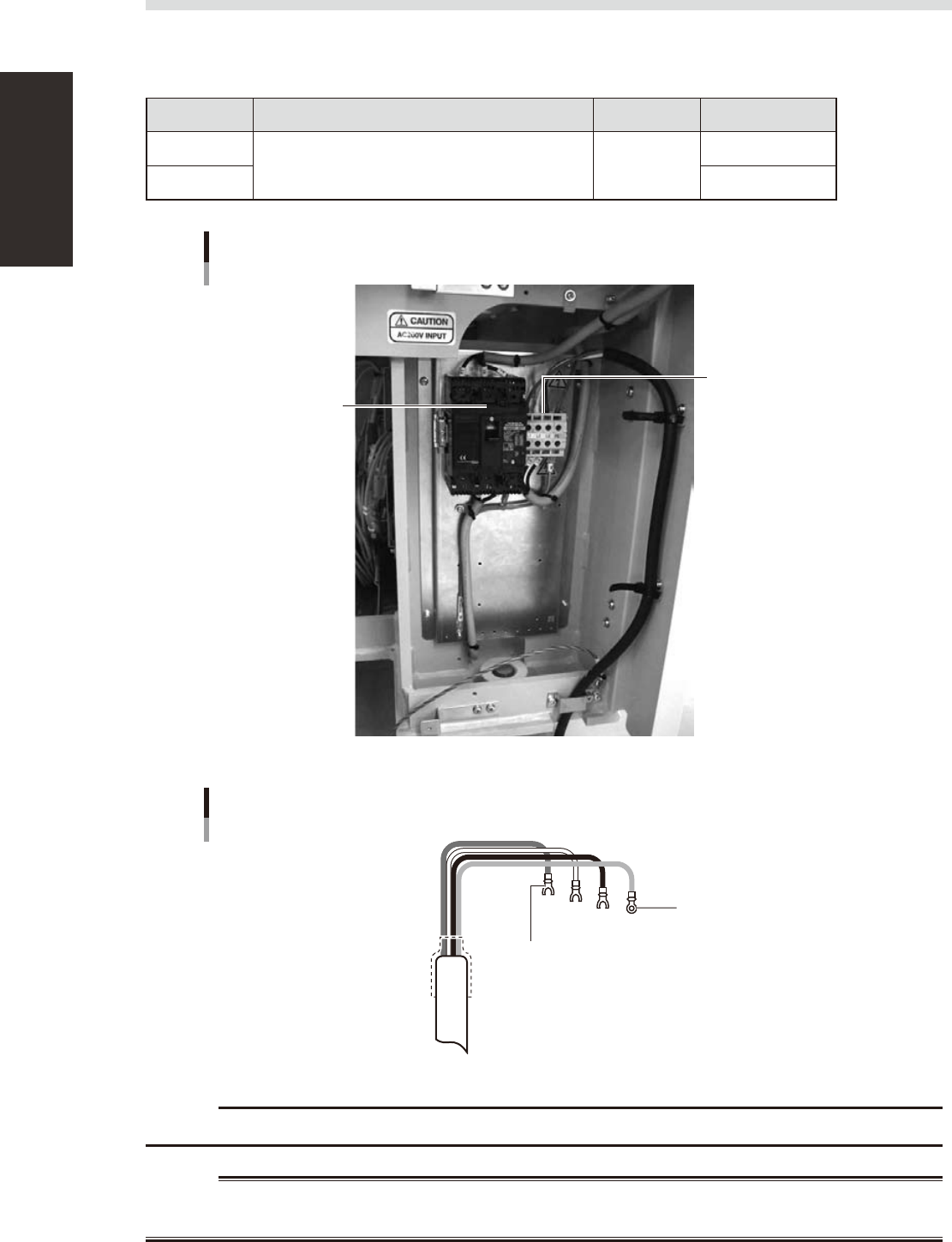
1.2 Power connection terminals
The power connection terminals are located inside the lower right panel on the front of the machine. Connect
the power cable leads as shown below to the L1, L2, L3 and ground terminal (PE) on the power terminal block.
n
Power supply specifications
Model name Power Frequency Power capacity
YS12
3-phase AC 200/208/220/240/380/400/416V (±10%) 50/60Hz
4.9KVA
YG12 3.9KVA
Power input terminals
(L1, L2, L3) and ground terminal
Main breaker
Power connection terminals
53433-L5-00
Fork-tongue crimp terminal
Power cable example
L1
L2
L3
PE
L=100mm
Ring-tongue crimp terminal
53434-L5-00
c
Use a power cable whose conductor cross-section area is greater than 2.5mm
2
.
w
WARNING

MAINTENANCE MANUAL
Aug. 2009
Version 1.00
© YAMAHA MOTOR CO., LTD. IM Operations
All rights reserved. No part of this publication may be
reproduced in any form without the permission of
YAMAHA MOTOR CO., LTD.
Information furnished by YAMAHA in this manual is believed to
be reliable. However, no responsibility is assumed for possible
inaccuracies or omissions. If you find any part unclear in this manual,
please contact YAMAHA or YAMAHA sales representatives.