00193922-01.pdf - 第159页
User Manual SIPLAC E HF Series 4 Setting up and commissioning Software Vers ion SR.505.xx 05/2004 US Edition 4.4 Infrastructure at the inst allation location 159 W A RNING The ele ctrical cables to each i ndividual machi…

4 Setting up and commissioning User Manual SIPLACE HF Series
4.4 Infrastructure at the installation location Software Version SR.505.xx 05/2004 US Edition
158
4.4.3.1 Danger notes
WARNING
The placement system is supplied with 3 x 208 VAC, 3 x 230 VAC, 3 x 380 VAC, 3 x 400 VAC or
3 x 415 VAC ± 5 %, 50/60 Hz main power voltage. This means that some parts of the system
carry potentially lethal voltages - even when switched off at the main power switch. Incorrect han-
dling of the placement system can therefore result in death or severe injury or considerable dam-
age to equipment.
Æ Always follow the applicable accident prevention and DIN regulations (particularly DIN EN 60
204, part 1).
Æ Only trained and qualified personnel may remove the cover over the power supply unit and
connect the machine to the power supply.
4
4
4.4.3.2 Checking the main power supply
Check that the main power supply conforms to the prescribed machine specifications (see table
in section 3.3
, page 91).
PLEASE NOTE:
The document entitled "Network configuration (electrical and compressed air) for SMD systems
on the customer's premises", part no. 00191409-xx, describes the action that can be taken to
meet the required specifications.
4
4
4
4.4.3.3 Power supply cable - specification
The following specifications apply to the power supply cable:
5 x 6 mm² for 3 x 380 VAC / 3 x 400 VAC / 3 x 415 VAC
5 x 6 mm² for 3 x 208 VAC / 3 x 230 VAC
The color coding for the wires will depend on the country in which the system is operated.
User Manual SIPLACE HF Series 4 Setting up and commissioning
Software Version SR.505.xx 05/2004 US Edition 4.4 Infrastructure at the installation location
159
WARNING
The electrical cables to each individual machine and to the installed options (e.g. MTC, produc-
tivity lift, vacuum pump) must be clearly identified and there must be no doubt as to their alloca-
tion. The regulations of the country in which the machine is operated apply.
4
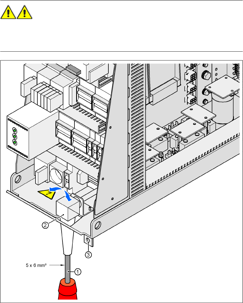
Fig. 4.4 - 3 Cross-section of the main power cable
4
(1) Power supply cable
(2) Angle for the cable gland
(3) Fixing strap for the power supply unit on the machine frame
4 Setting up and commissioning User Manual SIPLACE HF Series
4.4 Infrastructure at the installation location Software Version SR.505.xx 05/2004 US Edition
160
4.4.3.4 Connecting the power supply cable
4
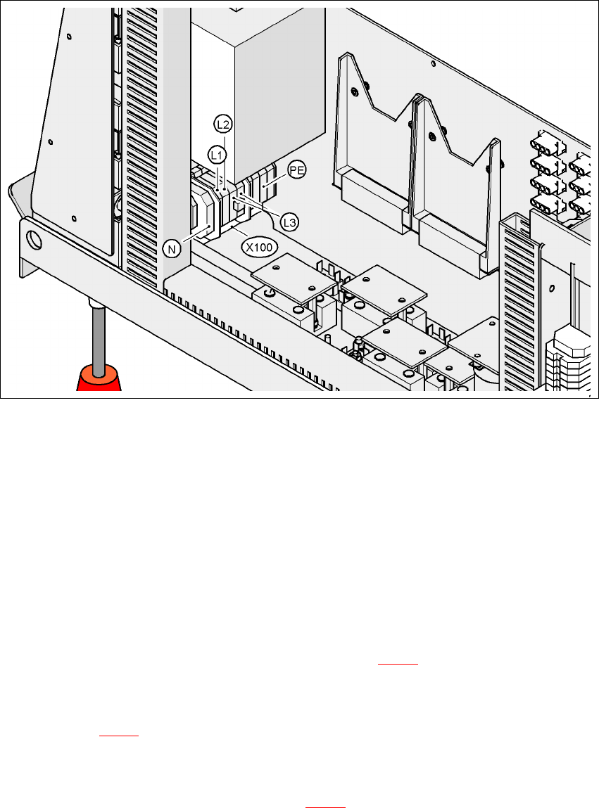
Fig. 4.4 - 4 Terminal panel for connecting the power cable
4
(L1) Three-phase
(L2) Three-phase
(L3) Three-phase
(N) Neutral conductor
(PE) Protective ground wire
(X100) Terminal panel
Æ Crimp a ferrule onto each end of the wire.
Æ Loosen the nuts on the angled cable gland (item 2 in Fig. 4.4 - 3).
Æ Fold up the angled cable gland.
Æ Feed the power supply cable through the angled cable gland to the terminal panel X100 (see
X100 in Fig. 4.4 - 4
).
Æ Connect the cable to the terminal and ensure that it has a sufficient bending radius. The wires
must not be kinked.
Æ Fold up the angled cable gland (item 2 in Fig. 4.4 - 3) and tighten the nuts hand-tight.