00193922-01.pdf - 第160页
4 Setting up and commissioning User Manual SIPLACE HF Series 4.4 Infrastructure at t he installation location Software Version SR. 505.xx 05/2004 US Edition 160 4.4.3.4 Conn ecting the power supply cable 4 Fig. 4.4 - 4 T…
User Manual SIPLACE HF Series 4 Setting up and commissioning
Software Version SR.505.xx 05/2004 US Edition 4.4 Infrastructure at the installation location
159
WARNING
The electrical cables to each individual machine and to the installed options (e.g. MTC, produc-
tivity lift, vacuum pump) must be clearly identified and there must be no doubt as to their alloca-
tion. The regulations of the country in which the machine is operated apply.
4
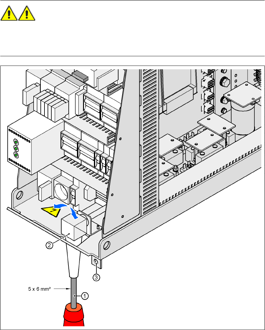
Fig. 4.4 - 3 Cross-section of the main power cable
4
(1) Power supply cable
(2) Angle for the cable gland
(3) Fixing strap for the power supply unit on the machine frame
4 Setting up and commissioning User Manual SIPLACE HF Series
4.4 Infrastructure at the installation location Software Version SR.505.xx 05/2004 US Edition
160
4.4.3.4 Connecting the power supply cable
4
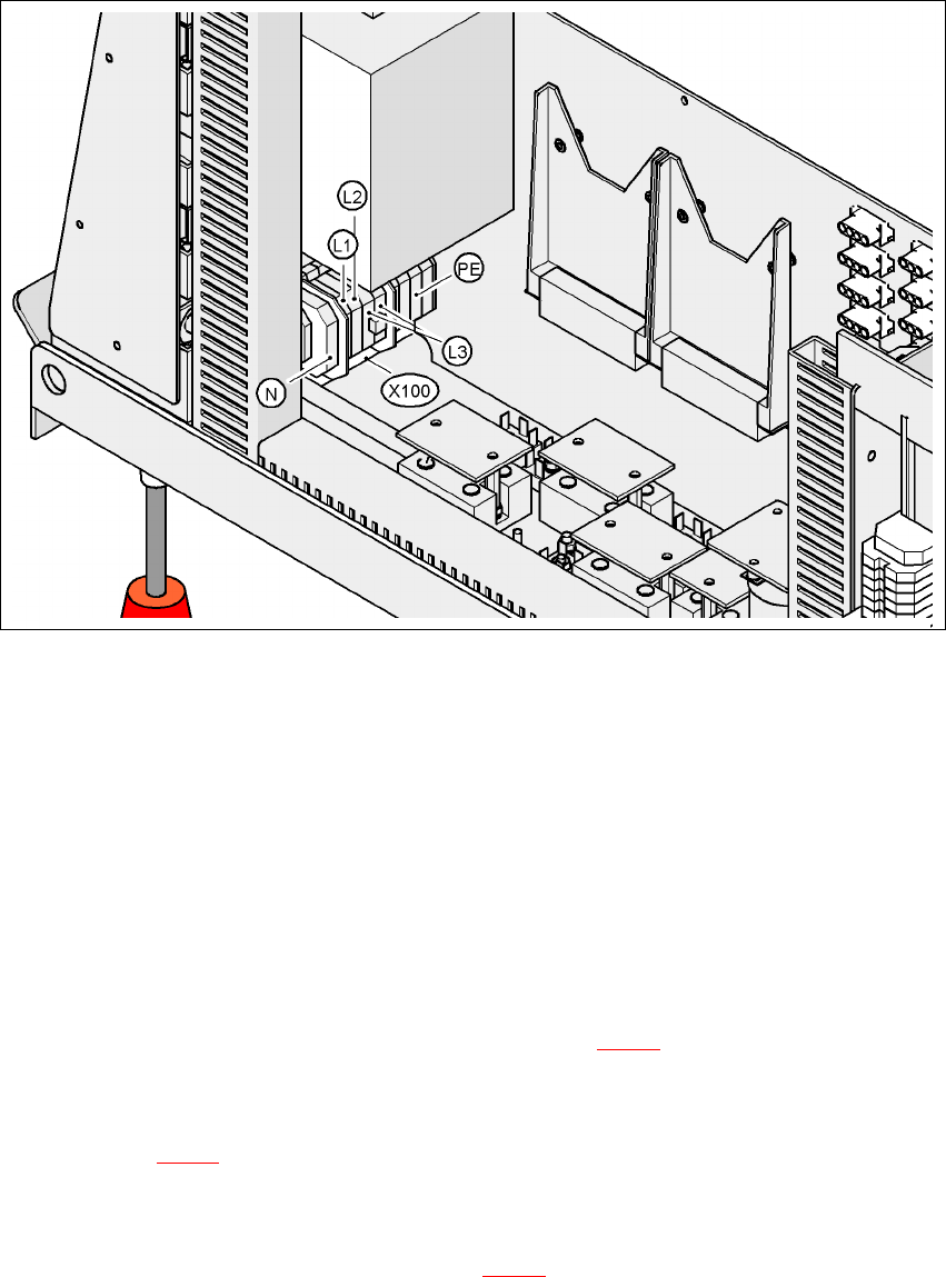
Fig. 4.4 - 4 Terminal panel for connecting the power cable
4
(L1) Three-phase
(L2) Three-phase
(L3) Three-phase
(N) Neutral conductor
(PE) Protective ground wire
(X100) Terminal panel
Æ Crimp a ferrule onto each end of the wire.
Æ Loosen the nuts on the angled cable gland (item 2 in Fig. 4.4 - 3).
Æ Fold up the angled cable gland.
Æ Feed the power supply cable through the angled cable gland to the terminal panel X100 (see
X100 in Fig. 4.4 - 4
).
Æ Connect the cable to the terminal and ensure that it has a sufficient bending radius. The wires
must not be kinked.
Æ Fold up the angled cable gland (item 2 in Fig. 4.4 - 3) and tighten the nuts hand-tight.
User Manual SIPLACE HF Series 4 Setting up and commissioning
Software Version SR.505.xx 05/2004 US Edition 4.4 Infrastructure at the installation location
161
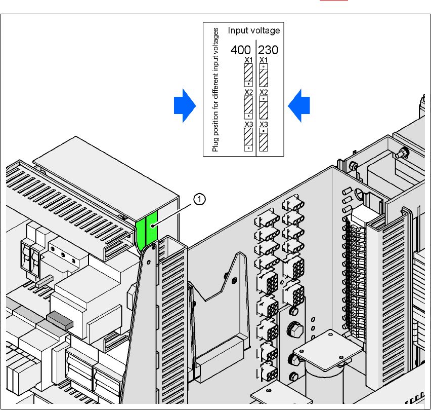
4.4.3.5 Checking the inrush current limitation jumpers
The inrush current limitation must be configured in relation to the supply voltage. This is done us-
ing plug-in jumpers on the inrush current limitation board (item 1 in Fig. 4.4 - 5
).
4
Fig. 4.4 - 5 Position of the board and connectors for the inrush current limitation
4
(1) Inrush current limitation board
X1, X2, X3 Connectors for configuring the inrush current limitation
Æ Check the jumper assignment and correct if necessary.
3 x 380 VAC
3 x 400 VAC
3 x 415 VAC
3 x 208 VAC
3 x 230 VAC