00193922-01.pdf - 第301页
User Manual SIPLAC E HF Series 7 Station extensions Software Version SR.505.xx 05/2004 US Edition 7.2 Component came ra for the TwinHead, FC camera 301 7.2.1.3 Position of the component vision cam eras for the T winHead …
7 Station extensions User Manual SIPLACE HF Series
7.2 Component camera for the TwinHead, FC camera Software Version SR.505.xx 05/2004 US Edition
300
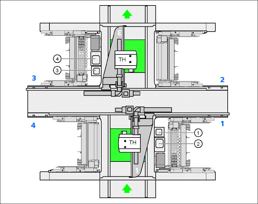
7.2.1.2 Position of the component vision cameras for the TwinHead on the HF placement
machine
7
Fig. 7.2 - 2 Position of the component vision cameras for the TwinHead on the HF placement machine
(1) Assembly position for the component vision camera (stationary, P&P (type 20) 8 x 8), location 1
(2) Assembly position for the component vision camera (stationary, P&P (type 22) 50 x 40), loca-
tion 1
(3) Assembly position for the component vision camera (stationary, P&P (type 20) 8 x 8), location 3
(4) Assembly position for the component vision camera (stationary, P&P (type 22) 50 x 40), loca-
tion 3
User Manual SIPLACE HF Series 7 Station extensions
Software Version SR.505.xx 05/2004 US Edition 7.2 Component camera for the TwinHead, FC camera
301
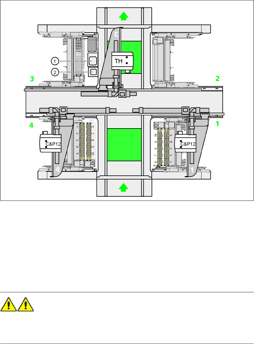
7.2.1.3 Position of the component vision cameras for the TwinHead on the HF/3 placement
machine
7
Fig. 7.2 - 3 Position of the component vision cameras for the TwinHead on the HF/3 placement machine
(1) Assembly position for the CO vision camera (stationary, P&P (type 22) 50 x 40), location 3
(2) Assembly position for the CO vision camera (stationary, P&P (type 20) 8 x 8), location 3
7.2.2 Safety instructions for the TwinHead component cameras
during a placement head change
WARNING 7
When the placement head is changed from the TwinHead to the Collect&Place head, the Twin-
Head's component vision cameras (stationary, P&P, type 22, 50 x 40, and type 20, 8 x 8) must be
removed, otherwise the Collect&Place head will collide with the camera housings.
7 Station extensions User Manual SIPLACE HF Series
7.3 Component barcode reader Software Version SR.505.xx 05/2004 US Edition
302
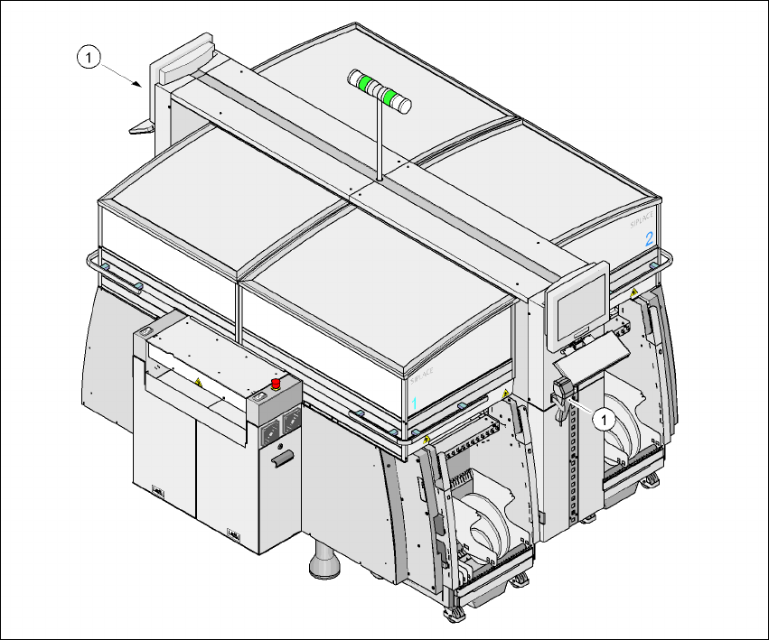
7.3 Component barcode reader
7.3.1 General
With the placement system, a barcode reader can be used to check that the track allocation is
correct and to read component data from component reels. A barcode reader can be installed on
both of the operator panels on the placement system. A retrofit kit contains two component bar-
code readers.
7
Fig. 7.3 - 1 Component barcode reader
(1) Barcode reader
Track allocation 7
Four-digit barcode strips are attached to the lateral safety screens for the purposes of track allo-
cation. The first digit is used to identify the component table (1, 2, 3, or 4), while the remaining
three digits specify the track number. There are also return barcodes at both ends of the barcode