00193922-01.pdf - 第316页
7 Station extensions User Manual SIPLACE HF Series 7.6 Ceramic substrate centering Software Version SR.505.xx 05/ 2004 US Edition 316 7.6.2.1 Structu re Fig. 7.6 - 1 Structure of the ceramic substrate centering unit (1) …
User Manual SIPLACE HF Series 7 Station extensions
Software Version SR.505.xx 05/2004 US Edition 7.6 Ceramic substrate centering
315
7.6 Ceramic substrate centering
7.6.1 General
Ceramic substrates are brittle, and therefore sensitive to the mechanical stresses that can occur
while clamping the PCBs for the placement process, for example. The machine should therefore
always be equipped with mechanical ceramic substrate centering for placing ceramic substrates.
Two mechanical centering devices are installed per conveyor track.
7.6.2 Mechanical centering
The ceramic substrate centering device is fitted to the lifting table. If the substrate has reached its
placement position, the lifting table moves up. When it reaches the top end position, the mechan-
ical ceramic substrate centering device is activated and the substrate is held in place on the PCB
conveyor. The mechanical centering is followed by optical centering with the PCB vision camera.
One particular advantage of ceramic substrate centering is that it allows the ceramic substrate to
be placed right up to the edge.
7 Station extensions User Manual SIPLACE HF Series
7.6 Ceramic substrate centering Software Version SR.505.xx 05/2004 US Edition
316
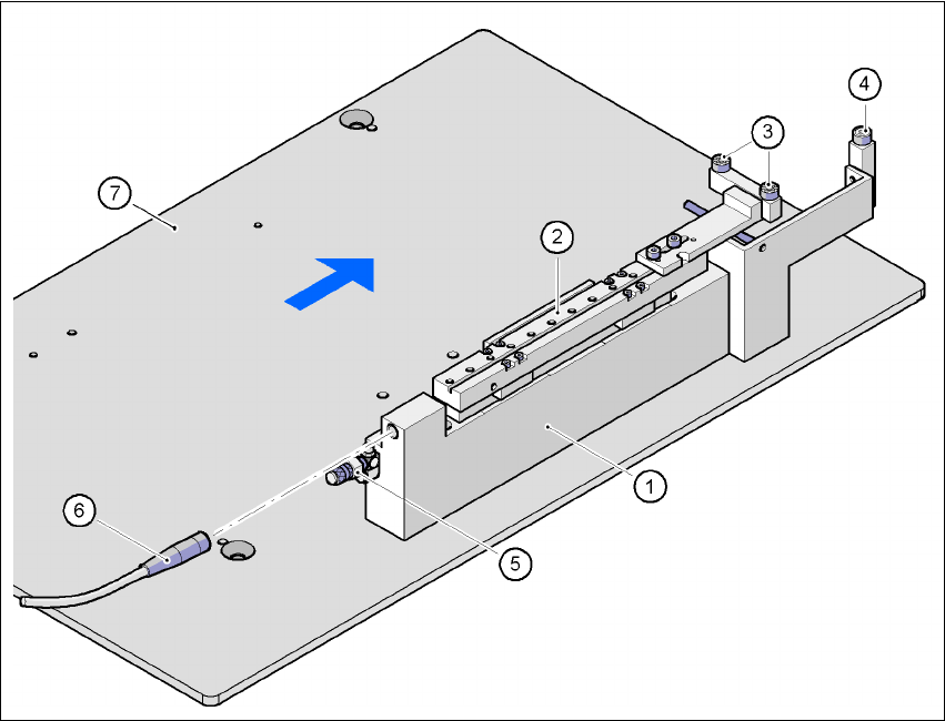
7.6.2.1 Structure
Fig. 7.6 - 1 Structure of the ceramic substrate centering unit
(1) Mechanical ceramic substrate centering
(2) Centering slide
(3) Ball bearing
(4) Stop
(5) Compressed air connection
(6) Proximity switch connecting cable
(7) Lifting table
7
7
7.6.2.2 Preventive maintenance
– Make sure to clean and grease the ball bearings in the X-axis centering unit.
– If necessary, check that the pneumatic driving mechanism is running smoothly.
– The conveyor should be maintained as described in the maintenance instructions.

User Manual SIPLACE HF Series 7 Station extensions
Software Version SR.505.xx 05/2004 US Edition 7.6 Ceramic substrate centering
317
7.6.2.3 Technical data
7
7.6.3 Optical centering
Optical centering uses fiducials for centering the PCBs. You should select either the PCB vision
camera or the multicolor PCB vision camera (type 18) 21, depending on the contrast ratio of the
fiducials (see Section 7.7
).
7.6.4 Fiducial shape recommendation for ceramic substrates
The contrast between the carrier package material and the circuit-board conductor layer is gener-
ally very small with ceramic substrates. The fiducials must therefore be selected with regard to
certain criteria concerning the fiducial shape and structure. Recommended fiducial shapes and
structures are given below.
7.6.4.1 Fiducial shape
We recommend a rectangle or square with an edge length of > 1 mm, and a clearance of > 0.5
mm.
Substrate format 50 x 50 mm² to 102 x 178 mm²
(2" x 2" to 4" to 7")
Substrate thickness Max. 1.5 mm
Substrate model Unscribed (without problems)
Scribed (requires testing)
Clamping
X direction (direction of travel)
Y direction
Z direction
Mechanical centering
< 1.5 mm, no clamping
> 1.5 mm by lifting table with > 50 N
Support on the conveyor 2.5 mm
Optical centering with the PCB vision camera:
Type of illumination for light pastes
Type of illumination for dark pastes and close
spacing to adjacent structures (> 1 mm):
PCB vision camera (standard)
Multicolor PCB vision camera (optional)
4 illumination levels to be selected
Fiducial criteria See PCB vision module position detection
PCB underside clearance 12 mm
Compressed air connection 0.55 MPa (5.5 bar)