00193922-01.pdf - 第56页
2 Operational safety User Manual SIPLACE HF Series 2.6 Safety equipment Software Version SR.505.xx 05/2004 US Edition 56 conveyo r is prote cted by c overs, whi ch can be p ivoted up wards, over the inpu t and ou tput be…
User Manual SIPLACE HF Series 2 Operational safety
Software Version SR.505.xx 05/2004 US Edition 2.6 Safety equipment
55
2.6 Safety equipment
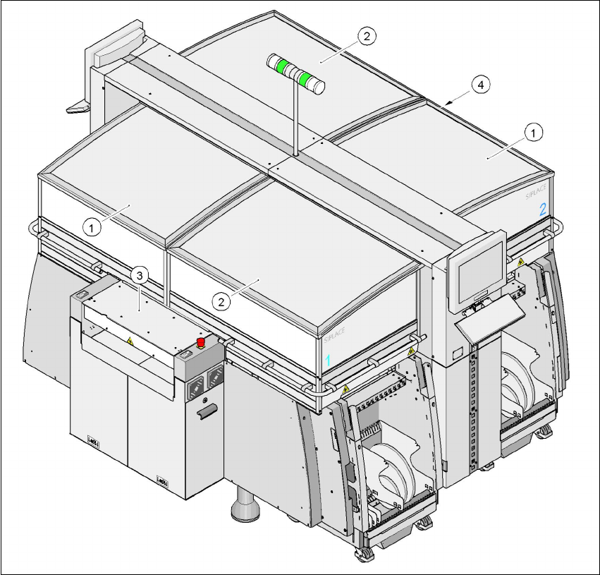
2.6.1 Protective covers
2
Fig. 2.6 - 1 Protective covers
2
The traveling range of the gantries has four protective covers that can be swung upwards. There
are side screens to prevent access to the inside of the machine from the side. Access to the PCB
(1)Protective cover, short
(2)Protective cover, long
(3)Cover and hand guard on the input belt
(4)Cover and hand guard on the output conveyor
2 Operational safety User Manual SIPLACE HF Series
2.6 Safety equipment Software Version SR.505.xx 05/2004 US Edition
56
conveyor is protected by covers, which can be pivoted upwards, over the input and output belts
and hand guards on both belts.
Function 2
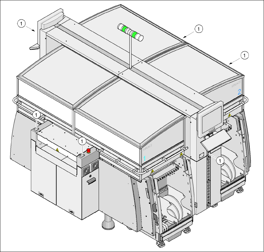
If one of the protective covers has been swung upwards or one of the covers on the PCB conveyor
has been lifted, the power supply to the gantry axes is cut off immediately. The gantry axes stop
moving. The message "Close cover" is displayed on the screen.
Æ Close the protective covers and press one of the Start buttons to continue placement.
2
Fig. 2.6 - 2 Position of the Start button (white) on the machine
(1) Start button (white) on the machine
User Manual SIPLACE HF Series 2 Operational safety
Software Version SR.505.xx 05/2004 US Edition 2.6 Safety equipment
57
2.6.2 Switches and buttons on the placement machine
2.6.2.1 Position of switches and buttons on the placement machine
2
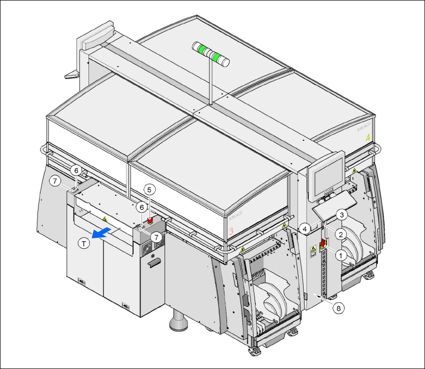
Fig. 2.6 - 3 Position of switches and buttons - View of the PCB output side
2
(1)Main power switch
(2)Stop button (black) on the operator panel on the power supply side
(3)Start button (white) on the operator panel on the power supply side
(4)Component counter on the operator panel on the power supply side
(5)Emergency stop button on the output side
(6)Start button (white) on the output side
(7)Stop button (white) on the output side
(8)Service socket in the power supply unit behind the cover
(T)PCB transport direction