00193922-01.pdf - 第170页
4 Setting up and commissioning User Manual SIPLACE HF Series 4.5 Setting up the placement machine Software Version SR.505.x x 05/2004 US Edition 170 Æ Carefu lly loos en the two hexa gon sock et head scr ews M24x9 0 (ite…
User Manual SIPLACE HF Series 4 Setting up and commissioning
Software Version SR.505.xx 05/2004 US Edition 4.5 Setting up the placement machine
169
Æ Screw the thread of the "HS50" machine foot into the hole on the underside of the spacer.
Æ Align the two spacers as follows:
– The opening in the spacer on the pneumatic unit side points in the direction of PCB trans-
port (see point 4 in Fig. 4.5 - 2
on page 166).
– The opening in the spacer on the power supply side points against the direction of PCB
transport (see point 3 in Fig. 4.5 - 2
on page 166).
Æ Fix each spacer using four hexagon socket head screws M12x80 (see point 4 in Fig. 4.5 - 4)
using the size 10 mm screwdriver bit.
4.5.4.2 Presetting the height of the machine feet
4
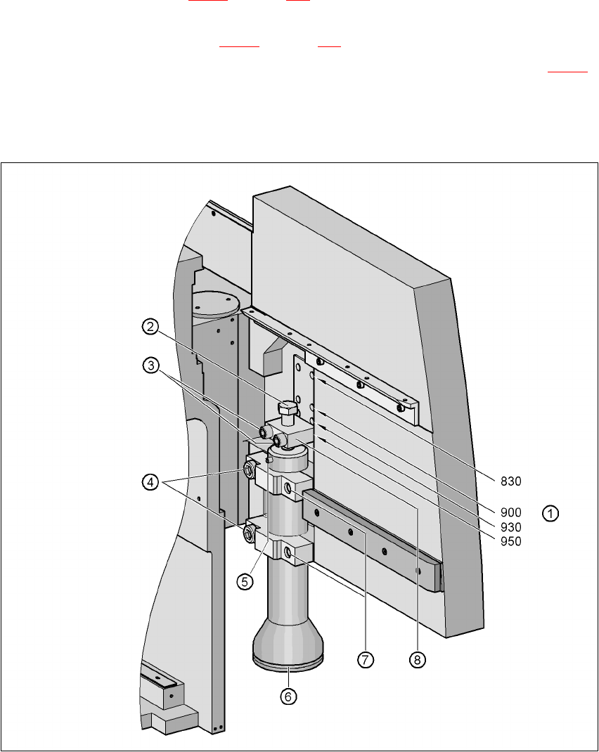
Fig. 4.5 - 5 Presetting the height of the machine feet

4 Setting up and commissioning User Manual SIPLACE HF Series
4.5 Setting up the placement machine Software Version SR.505.xx 05/2004 US Edition
170
Æ Carefully loosen the two hexagon socket head screws M24x90 (item 4 in Fig. 4.5 - 5) using the
19 mm bit, and allow the machine foot (item 6 in Fig. 4.5 - 5
) to slide down slowly until the lock-
ing pin (item 5 in Fig. 4.5 - 5
) is lying on the clamp (item 7 in Fig. 4.5 - 5).
Æ Use the 14 mm bit to loosen the two hexagon socket head screws M16x90 (item 3 in Fig. 4.5
- 5), and remove the height adjustment block (item 8 in Fig. 4.5 - 5).
Æ Use the size 36 open-ended spanner to screw the hexagon head screw M24x80 (item 2 in Fig.
4.5 - 5
) in or out of the block (item 8 in Fig. 4.5 - 5) until the same length of screw thread
emerges on both sides of the block.
Æ Fix the height adjustment block (item 8 in Fig. 4.5 - 5) at the desired height of 830 mm, 900
mm, 930 mm or 950 mm (item 1) using the two hexagon socket head screws M16x90 (item 3).
Æ Set the height for each machine foot.
Æ Now use the fork-lift to carefully lower the placement machine until the machine feet touch the
floor evenly. There should always be a second person present to ensure that the machine re-
mains stable while it is being lowered. It may be necessary to loosen the machine foot clamps
slightly.
Æ Continue lowering the machine until the machine foot touches the hexagon head screw
M24x80 (item 2) for adjusting the height.
Æ Make sure that the "HS50" machine feet (see point 2 in Fig. 4.5 - 2) do not yet touch the floor.
If necessary, screw the "HS50" machine feet into the machine or spacer slightly.

User Manual SIPLACE HF Series 4 Setting up and commissioning
Software Version SR.505.xx 05/2004 US Edition 4.5 Setting up the placement machine
171
4.5.5 Fitting the extension kits to the machine frame
4.5.5.1 Fitting the extension kit on the PCB input side
When the placement machine is delivered, the extension kits on the PCB input side and PCB input
conveyor are dismantled. The procedure for attaching the extension kit to the PCB input side is
as follows:
– Fitting the input conveyor
see Section 4.5.6, page 172
– Fitting the extension kit on the PCB input side see Section 4.5.7, page 174
– Installing the computer unit on HF and HF/3 see Section 4.5.8, page 178
– Installing the axis unit on the HF and HF/3 see Section 4.5.12, page 192
– Fitting the main fault indicator see Section 4.5.13, page 196
– Integrating the placement machine into the line see Section 4.5.14, page 196
– Making final adjustments to the placement machine see Section 4.5.15, page 200
4.5.5.2 Fitting the extension kit on the PCB output side
If the extension kit on the PCB output side was also removed for ease of transportation, you will
have to carry out the following steps before integrating the placement machine into the line (see
Section 4.5.14
, page 196):
– Fitting the output conveyor
see Section 4.5.10, page 186
– Fitting the extension kit on the PCB output side see Section 4.5.11, page 188
– Installing the axis unit on the HF and HF/3 see Section 4.5.12, page 192
– Fitting the main fault indicator see Section 4.5.13, page 196
– Integrating the placement machine into the line see Section 4.5.14, page 196
– Making final adjustments to the placement machine see Section 4.5.15, page 200