00193922-01.pdf - 第235页
User Manual SIPLAC E HF Series 6 Component han dling Software Version SR.505.xx 05/2004 US Edition 6.2 Technical data for the feeders 235 6.2 T echnical dat a for the feeders The follo wing pages contain di agrams of all…
6 Component handling User Manual SIPLACE HF Series
6.1 Feeders Software Version SR.505.xx 05/2004 US Edition
234
6.1.1 Safety instructions
for processing capacitors based on powdered metal
There is a risk associated with processing capacitors based on powdered metal (e.g. tantalum).
The risk is that
– an exothermic reaction, i.e. a sudden build-up of heat, may occur, if these components are
damaged. If the ambient conditions are unfavorable, and depending on the capacitance, this
build-up of heat can cause damage.
– This effect can occur when these components are cut.
Please contact your suppliers to clarify whether the components that you handle are affected.
In extremely rare cases, this risk can occur in the tape cutter of SIPLACE machines, with the re-
mote possibility of causing a smoldering fire in the waste tape.
The ambient conditions are unfavorable if:
(1) The components remain on the tape while the set tape cycle is checked (since the operator
can cycle the feeder onward without removing components during this check).
(2) The components remain on the tape, e.g. due to a tear in the cover foil.
(3) The components remain on the tape, and the components or tape do not conform to the
specification, thus increasing the pick-up error rate.
Please follow the instructions given below to minimize the risk when placing capacitors based on
powdered metal.
(1) If the component tape is cycled onward manually, the operator must remove any components
remaining in the tape pocket.
(2) If the cover foil tears, the operator must remove any components remaining on the tape.
(3) The waste tape container must be emptied regularly (recommended interval: every hour).
6
WARNING
To avoid the risk, it is essential to use only feeders that have
been approved for placing such components, namely:
for model C/D item no.: 00141118-01
for model E item no.: 00141117-01 6
6
The feeders are labeled as shown
below:
6
User Manual SIPLACE HF Series 6 Component handling
Software Version SR.505.xx 05/2004 US Edition 6.2 Technical data for the feeders
235
6.2 Technical data for the feeders
The following pages contain diagrams of all the feeders, technical data and the feeder setting op-
tions on the placement system.
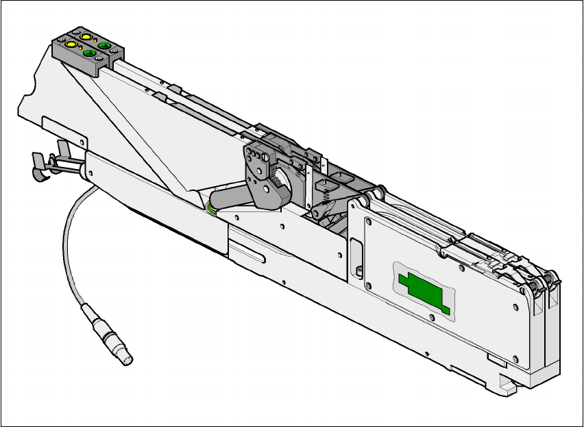
6.2.1 8 mm S II feeder
Fig. 6.2 - 1 8 mm S II feeder
Item no. 00141096-xx 6
Width 30.6 mm 6
Tracks per feeder 2 6
Assigned locations 1 6
Maximum number of feeders 4 x 15 6
Stock of components for 7" reels approx. 4000 6
Transport distance (variable) 2mm / 4mm 6
6 Component handling User Manual SIPLACE HF Series
6.2 Technical data for the feeders Software Version SR.505.xx 05/2004 US Edition
236
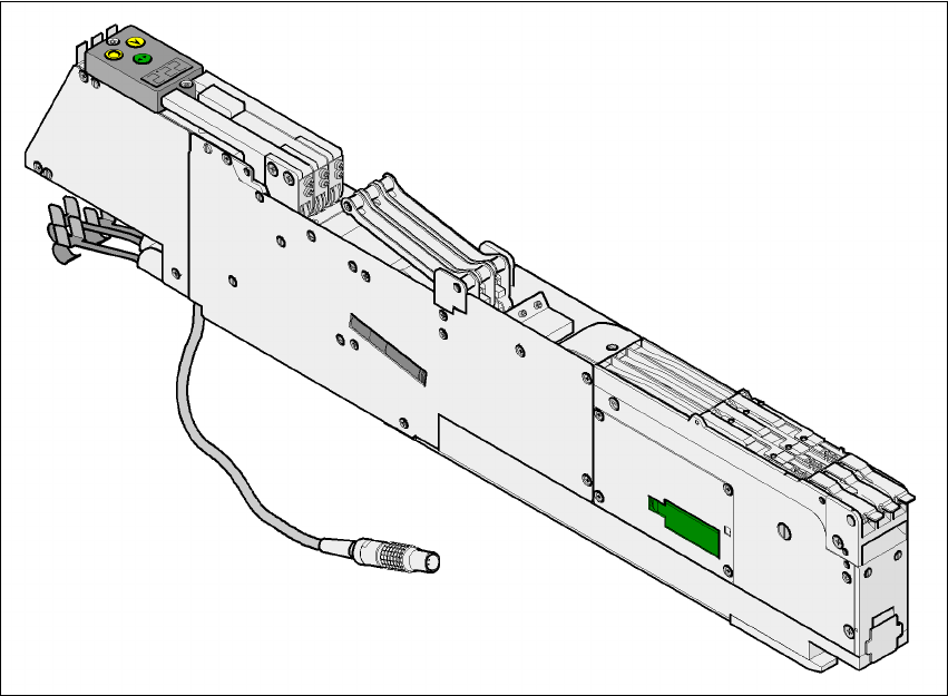
6.2.2 3 x 8 mm S feeder
Fig. 6.2 - 2 3 x 8 mm S feeder
Item no. 00141098-xx 6
Width 30.6 mm 6
Tracks per feeder 3 6
Assigned locations 1 6
Maximum number of feeders 4 x 15 6
Stock of components for 7" reels approx. 4000 6
Transport distance (variable) 2mm / 4mm 6