00193922-01.pdf - 第299页
User Manual SIPLAC E HF Series 7 Station extensions Software Version SR.505.xx 05/2004 US Edition 7.2 Component came ra for the TwinHead, FC camera 299 7.2 Component camera for t h e T w inHead, FC camera 7.2. 1 S tr uct…
7 Station extensions User Manual SIPLACE HF Series
7.1 Nozzle changer Software Version SR.505.xx 05/2004 US Edition
298
7
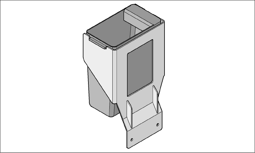
Fig. 7.1 - 22 Component reject bin
7.1.4 Grippers and special nozzles
The SIPLACE placement machines can process components based on through hole technology
and odd-shaped (OSC) components, in addition to the standard SMT spectrum. SIEMENS L&A
also continuously develops special nozzles and grippers in parallel.
Special nozzles are available for all placement heads in order to process placement jobs with max-
imum speed, precision and flexibility. The use of automatic nozzle changers also reduces the set-
up times that occur at a product change.
SIEMENS L&A can provide mechanical grippers for Pick&Place heads. If a component's surface
is not suitable for sucking up with nozzles, then it can be picked up and placed with mechanical
grippers. There are two types of gripper, and their functions can be divided into two groups:
– Grippers that grip the component at its outer edges and
– Grippers that grip the component at its inner edge.
Information on special nozzles and grippers is available from SIEMENS L&A. For the production
of special magazines and grippers, again contact SIEMENS L&A.
User Manual SIPLACE HF Series 7 Station extensions
Software Version SR.505.xx 05/2004 US Edition 7.2 Component camera for the TwinHead, FC camera
299
7.2 Component camera for the TwinHead, FC camera
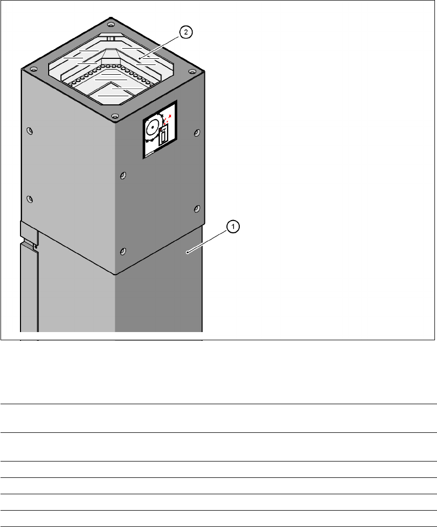
7.2.1 Structure of the CO camera (stationary, P&P (type 20) 8 x 8), FC camera
7
Fig. 7.2 - 1 Component vision camera for the TwinHead (stationary, P&P, type 20, 8 x 8), FC camera
7.2.1.1 Technical data
7
(1)Camera housing with integral camera and
camera amplifier
(2) Glass plate - over the illumination and lens
levels
Component dimensions 0.6 x 0.3 mm² up to 8 x 8 mm² for single component measure-
ment
Range of components 0201 to SO, PLCC, QFP, sockets, plugs, BGA, special compo-
nents, bare dies, flip-chips, shields
Min. lead pitch 0.25 mm
Min. ball/bump diameter 0.08 mm
Field of vision 11 x 11 mm²
Method of illumination Front-lighting (6 levels, programable as required)
7 Station extensions User Manual SIPLACE HF Series
7.2 Component camera for the TwinHead, FC camera Software Version SR.505.xx 05/2004 US Edition
300
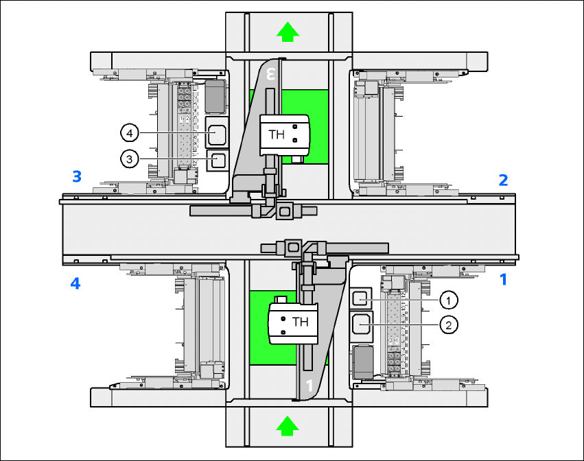
7.2.1.2 Position of the component vision cameras for the TwinHead on the HF placement
machine
7
Fig. 7.2 - 2 Position of the component vision cameras for the TwinHead on the HF placement machine
(1) Assembly position for the component vision camera (stationary, P&P (type 20) 8 x 8), location 1
(2) Assembly position for the component vision camera (stationary, P&P (type 22) 50 x 40), loca-
tion 1
(3) Assembly position for the component vision camera (stationary, P&P (type 20) 8 x 8), location 3
(4) Assembly position for the component vision camera (stationary, P&P (type 22) 50 x 40), loca-
tion 3