00193922-01.pdf - 第67页
User Manual SIPLAC E HF Series 2 Operational safety Software Vers ion SR.505.xx 05/2004 US Edition 2.6 Safety equipment 67 2 Fig. 2.6 - 9 EMERGENCY STOP loops Start button pressed Compressed air min. 0.5 MPa (5.0 bar)? N…
2 Operational safety User Manual SIPLACE HF Series
2.6 Safety equipment Software Version SR.505.xx 05/2004 US Edition
66
2.6.5.2 Structure of the signaling circuit
The six signaling contacts for the covers are connected in parallel and form the "cover signal" cir-
cuit. If one or more covers are opened, the contacts close, and the 24 V signal reaches the CAN
bus and signals that one of the covers is open.
The two signaling contacts for the EMERGENCY STOP buttons are connected in parallel and form
the "emergency stop push-button signal circuit". When an emergency stop button is pressed, a
24 V signal is sent to the CAN bus and signals that one of the emergency stop buttons has been
pressed. The four signaling contacts for the cover flaps over the push-buttons are connected in
parallel. They form the "Flap signal" circuit. If one or more cover flaps is raised, a 24 V signal is
applied to the CAN bus and signals that one of the cover flaps is not closed.
The four signaling contacts of the component trolley are polled individually. If a component trolley
is missing, it is located and displayed on the monitor. All 4 component trolleys must be docked in
to form the
"M-COTable" signal. The signal at the CAN bus input is then approx. 16V. If a component trolley
is missing, the signal voltage is 0 V.
2.6.5.3 Description of the functions of the emergency stop loops
The following conditions must be fulfilled in order to start and operate the placement machine:
– all four component trolleys must be docked in and connected.
– all covers - four over the gantries, one over the PCB input belt and one over the output belt -
must be closed.
– both emergency stop buttons must be released.
– the cover flaps (option) over the feeders must be closed.
– the minimum operating pressure must have been reached.
– the "software enable" signal must be active. This ensures that the safety circuit is closed.
– the power supply must be sending 24 V to the Start buttons and the protective contactor com-
bination.
– If one of the Start buttons is now pressed, the protective contactor combination PCC K6 will
switch and activate the following components:
– 250 VDC link voltage for the servo amplifiers for the gantry axes
– 145 VDC link voltage for the star axes
– the axis unit receives a "Servo enable" signal for the servo amplifiers
– 34 VDC operating voltage is switched to the component trolleys.
– 24 VDC operating voltage is switched to the used tape cutters.
– the PCB conveyor control receives the enable signal for the PCB clamping, the PCB stop-
per and the lifting table control.
The machine is then ready for use.
User Manual SIPLACE HF Series 2 Operational safety
Software Version SR.505.xx 05/2004 US Edition 2.6 Safety equipment
67
2
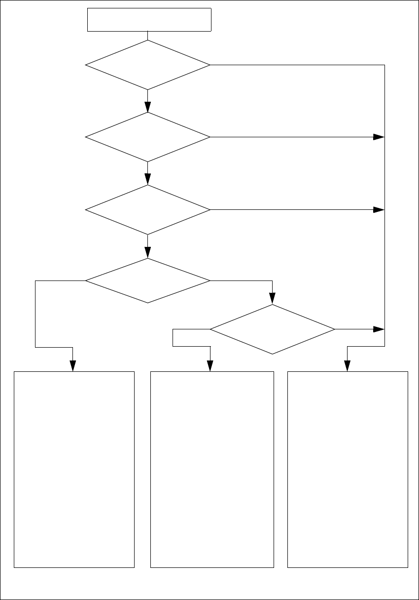
Fig. 2.6 - 9 EMERGENCY STOP loops
Start button pressed
Compressed air
min. 0.5 MPa
(5.0 bar)?
No
EMERGENCY STOP button
pressed?
Protective cover open ?
Barrier
activated on the user
interface?
No
Component
trolley emerg. stop circuit
interrupted?
Yes
No
No
Yes
Yes
No
2
Active
PCC*) Yes
Voltage
Y axis 250 VDC
X axis 250 VDC
Star axis 145 VDC
DP axis 40 VDC
Z axis 40 VDC
Active
PCB conveyor Yes
Lifting table Yes
PCB clamping Yes
Width adjustment Yes
Laser light barrier Yes
Used tape cutter Yes
CO trolley docking unit Yes
Yes
2
Active
PCC*) No
Voltage
Y axis 0 V
X axis 0 V
Star axis 0 VDC
DP axis 40 VDC
Z axis 40 VDC
Active
PCB conveyor Yes
Lifting table No
PCB clamping No
Width adjustment Yes
Laser light barrier No
Used tape cutter No
CO trolley docking unit Yes
2
Active
PCC*) No
Voltage
Y axis 0 V
X axis 0 V
Star axis 0 VDC
DP axis 40 VDC
Z axis 40 VDC
Active
PCB conveyor No
Lifting table No
PCB clamping No
Width adjustment No
Laser light barrier No
Used tape cutter No
CO trolley docking unit No
*) PCC protective contactor combination K6
Yes
2 Operational safety User Manual SIPLACE HF Series
2.6 Safety equipment Software Version SR.505.xx 05/2004 US Edition
68
2.6.6 Hand guard at the component trolley locations
WARNING 2
All locations must be equipped with feeders in order to guarantee operational reliability.
If there are not enough feeders available, unassigned locations should be fitted with a hand
guard (dummy feeder). When a waffle-pack tray (manual tray) is set up, the remaining locations
should again be protected with a hand guard.
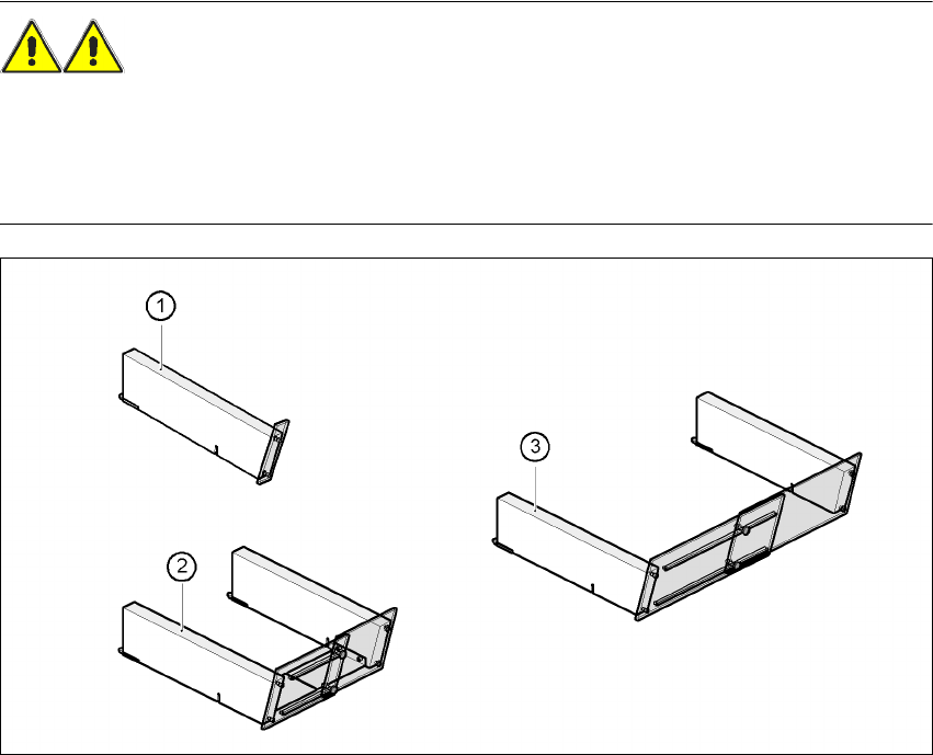
Fig. 2.6 - 10 Hand guard for component trolleys
2
(1) Hand guard for 1 location item no. 00116961-01
(2) Hand guard for 6 to 10 locations item no. 00116962-01
(3) Hand guard for 11 to 20 locations item no. 00116963-01