00193922-01.pdf - 第75页
User Manual SIPLAC E HF Series 2 Operational safety Software Vers ion SR.505.xx 05/2004 US Edition 2.9 Energy s tate of the mac hine after switching off at the main power sw itch 75 2 Fig. 2.9 - 3 Position of the compute…
2 Operational safety User Manual SIPLACE HF Series
2.9 Energy state of the machine after switching off at the main power switch Software Version SR.505.xx 05/2004 US Edition
74
2
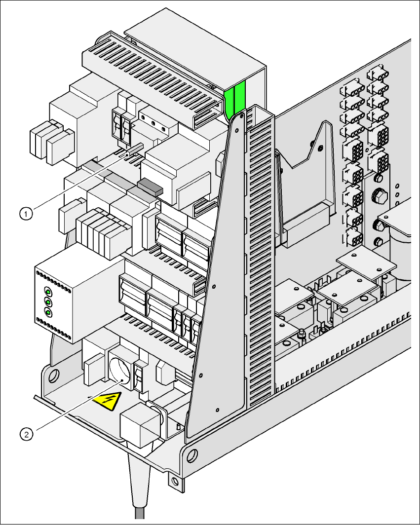
Fig. 2.9 - 2 Position of main power switch and service socket
2
(1) Main power switch
(2)Service socket
User Manual SIPLACE HF Series 2 Operational safety
Software Version SR.505.xx 05/2004 US Edition 2.9 Energy state of the machine after switching off at the main power switch
75
2
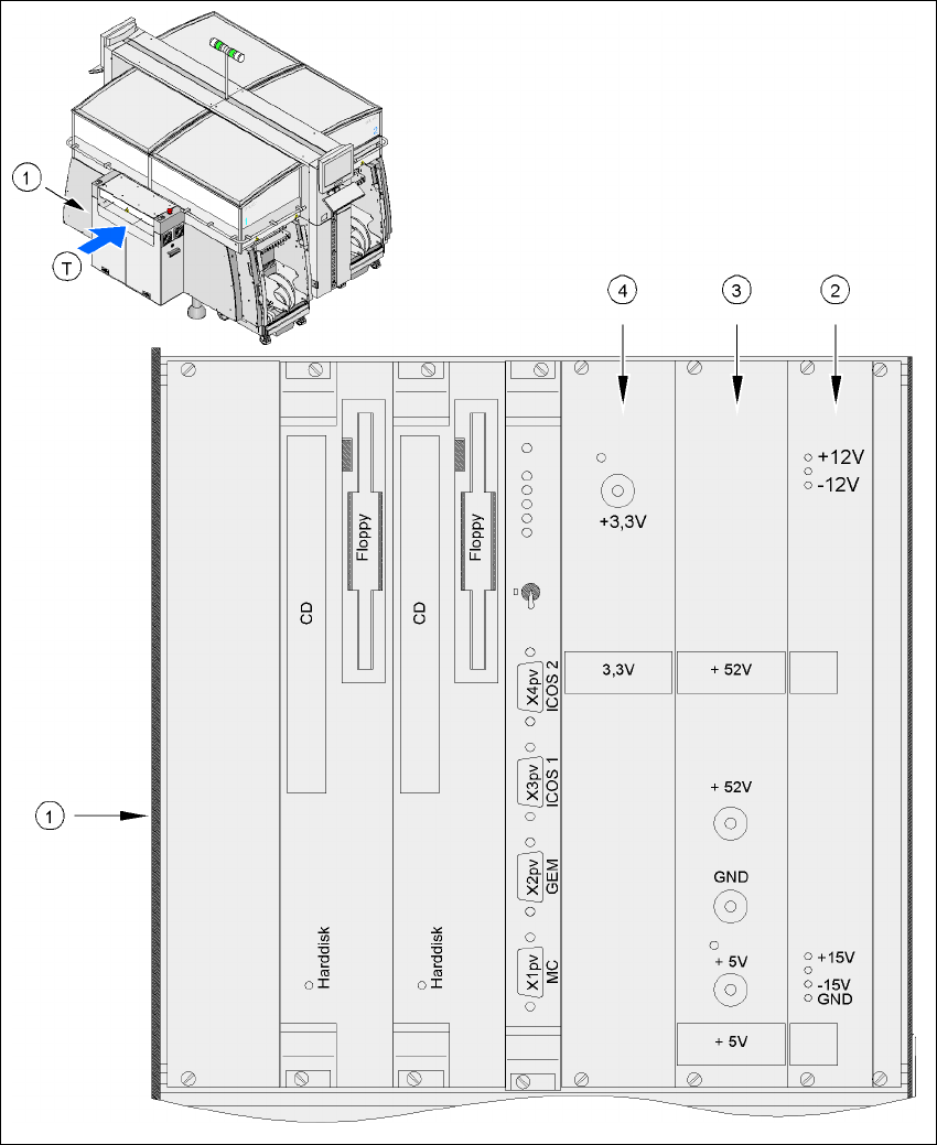
Fig. 2.9 - 3 Position of the computer unit
2
(1)Computer unit (top part)
(2)Power supply unit ± 12 V-/± 15 V-
(3)Power supply unit + 5 V-/+ 52 V-
(4)Power supply unit + 3.3 VDC
(T)Direction of PCB transport
2 Operational safety User Manual SIPLACE HF Series
2.9 Energy state of the machine after switching off at the main power switch Software Version SR.505.xx 05/2004 US Edition
76
2.9.1 Placement system switched off at the main switch, but still connected ...
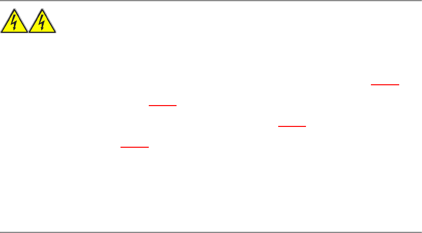
WARNING
The following components still carry potentially lethal voltages even if the main power switch is
switched off:
– Cable connecting terminals L1, L2, and L3 in the main power switch Q1 (see Fig. 2.9 - 4
)
– Service socket X102 (see Fig. 2.9 - 4
)
– Automatic circuit breaker F1 for the service socket (see Fig. 2.9 - 4
)
– Mains filter Z1 (see Fig. 2.9 - 4
)
– Terminal panel X100 for connecting the power supply cable
– The color of all individual wires, which still carry potentially lethal voltages even if the main
power switch is switched off, is brown.
– Axis unit