00193922-01.pdf - 第263页
User Manual SIPLAC E HF Series 6 Component han dling Software Vers ion SR.505.xx 05/2004 US Edition 6.3 Component trolley 263 6.3.4.1 T ape cont ainer assembly positi ons in the component trolley The tape con tainer is g…
6 Component handling User Manual SIPLACE HF Series
6.3 Component trolley Software Version SR.505.xx 05/2004 US Edition
262
6.3.4 Tape container
The tape container can hold reels up to 19" in diameter. You should use spindles to process reels
of 15" diameter or more. Insertion of the dividing plates is described in section 5.3
page 213.
PLEASE NOTE
For optimum operation, we recommend the use of spindles for 5" diameter or more.
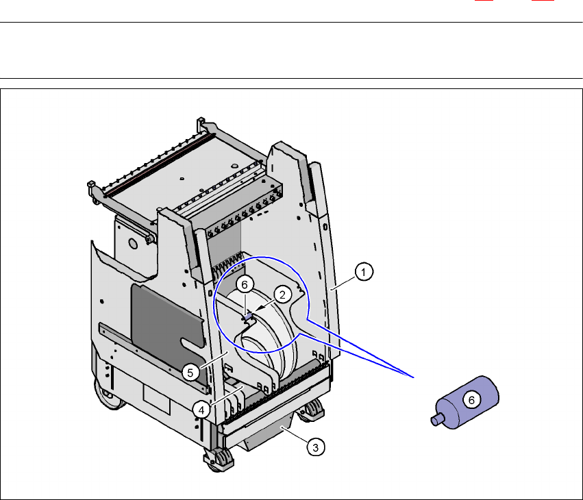
Fig. 6.3 - 5 Component trolley with tape container
(1) Component trolley
(2) Position of the spindles
(3) Waste tape container
(4) Tape container
(5) Dividing plate
(6) Spindle (enlarged)
User Manual SIPLACE HF Series 6 Component handling
Software Version SR.505.xx 05/2004 US Edition 6.3 Component trolley
263
6.3.4.1 Tape container assembly positions in the component trolley
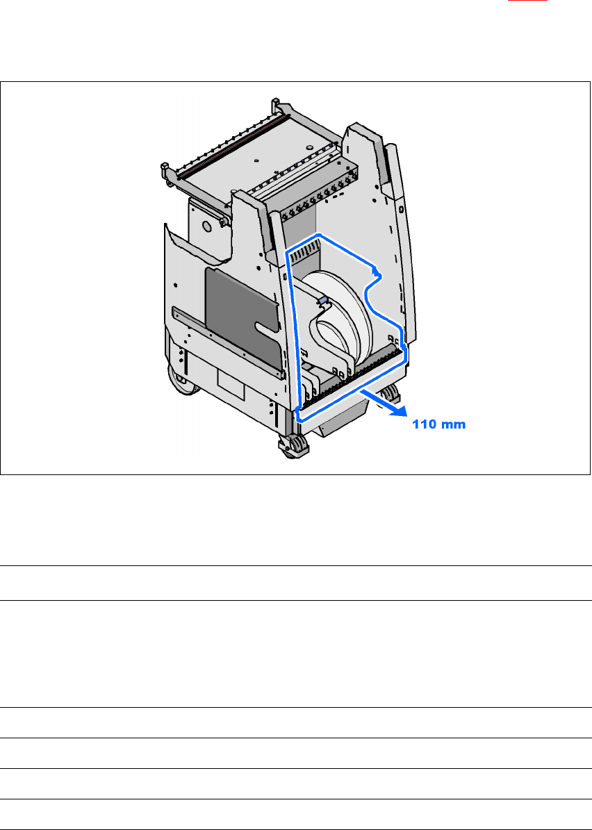
The tape container is generally fully integrated into the component trolley (see Fig. 6.3 - 5). By
loosening four screws, however, it can be moved so that it projects 110 mm out of the component
trolley. In this way, tape reels up to 19" in diameter can be used, even for a PCB transport height
of 830 mm.
6
Fig. 6.3 - 6 Moving the tape container
6.3.4.2 Tape reel diameter in relation to the PCB transport height
6
Option – – With support for 3rd tape reel
PCB transport
height of the
component
trolley
Tape container
fully integrated
into the
component
trolley
Tape container
moved forward
110 mm
Tape container
fully integrated
into the
component
trolley
Tape container
moved forward
110 mm
830 mm 17" 19" 15" 15"
900 mm 19" 19" 17" 17"
930 mm 19" 19" 17" 17"
950 mm 19" 19" 19" 19"

6 Component handling User Manual SIPLACE HF Series
6.3 Component trolley Software Version SR.505.xx 05/2004 US Edition
264
6.3.5 External power supply for component trolley
To keep the time required for a setup change as short as possible, component trolleys can be set
up in advance at a special external location. The feeder functions and settings can be checked
there to prepare them for operation. We provide an external power supply for this purpose. It is
used to supply the component trolley with the required electrical power and compressed air.
Technical data
The kit contains a main power cable to European standards, a main power cable to US standards
and a connecting cable between the power supply and the component trolley.
6.3.6 Compressed air supply for bulk case feeder
Bulkcase feeders require compressed air to operate. We therefore offer a compressed air supply
for bulkcase feeders as an optional extra.
It is easy to fit. First remove the sealing plug (item 1) from the compressed air connection on the
component feeder table (item 2). Then use two screws DIN 912, M8x20 (item 4) to fix the com-
pressed air supply (item 3) to the component feeder table (item 2). The compressed air supply has
retaining clips (item 5) on the back. These secure the bulk case feeder to the component trolley
and ensure that the compressed air supply is working properly.
Mains voltage 230 VAC ± 5 %
120 VAC ± 5 %
Compressed air connection Max. 1.0 MPa (10 bar)
Output pressure Can be regulated with a valve