00193922-01.pdf - 第320页
7 Station extensions User Manual SIPLACE HF Series 7.7 Multicolor PCB camera (type 18) 21 Software Version S R.505.xx 05/2004 US E dition 320 – White lighting This type of illumina tion is u sed for standar d PCBs with t…
User Manual SIPLACE HF Series 7 Station extensions
Software Version SR.505.xx 05/2004 US Edition 7.7 Multicolor PCB camera (type 18) 21
319
7.7 Multicolor PCB camera (type 18) 21
7.7.1 General
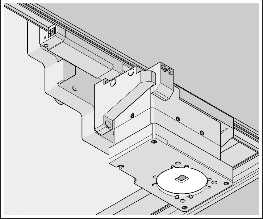
As an option, a multicolor PCB camera can be installed in place of the sub-gantry camera. The
multicolor PCB camera offers four different types of illumination. This greatly increases fiducial de-
tection and thus the centering accuracy.
7
Fig. 7.7 - 1 Multi-color PCB camera
7.7.2 Type of illumination
The following types of illumination can be selected on the multicolor PCB camera:
– Standard lighting
This mixture of white and infrared lighting can be used to detect a broad range of fiducials. The
image contrast can be improved by varying the illumination, thus optimizing the centering of
different fiducials.
7 Station extensions User Manual SIPLACE HF Series
7.7 Multicolor PCB camera (type 18) 21 Software Version SR.505.xx 05/2004 US Edition
320
– White lighting
This type of illumination is used for standard PCBs with tinned fiducials.
– Blue oblique lighting
In most cases, this can be used to greatly improve the contrast with bright fiducials on a light
base material, such as ceramic or CEM. Fiducials covered with solder resist can also be de-
tected better on a light background.
– Infrared lighting
This type of illumination is particularly useful for fiducials that are covered with solder resist or
for fiducials on flex materials. It is also sometimes possible to improve detection of silver/plat-
inum fiducials on ceramic. This should be tested by carrying out a test centering or placement
run.
User Manual SIPLACE HF Series 7 Station extensions
Software Version SR.505.xx 05/2004 US Edition 7.8 PCB alignment
321
7.8 PCB alignment
7.8.1 General
PCBs to be processed sometimes have a length to width ratio of 1:2 or worse. This means that
the shorter side of the PCB points in the direction of travel. During travel, such PCBs may twist
slightly and, as a result, the fiducials no longer lie within the PCB vision camera's search window.
In this case, the "PCB alignment" option ensures that these PCBs are realigned precisely at the
stopping position.
If PCBs with recesses in the direction of travel are processed, this may result in different process-
ing positions on machines with mechanical stoppers (HS-50, S-25 HM, F5 HM) and on machines
that monitor this position with laser light barriers (HF, HS-60, S-27 HM). The "PCB alignment" op-
tion ensures that the PCBs are stopped at the same position on all PCB conveyors. The "PCB
alignment" option is available for both single and dual conveyors.
7
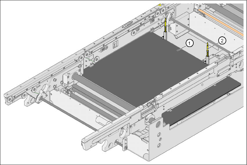
Fig. 7.8 - 1 PCB alignment
(1)Lifting table
(2)PCB stop