00193922-01.pdf - 第200页
4 Setting up and commissioning User Manual SIPLACE HF Series 4.5 Setting up the placement machine Software Version SR.505.x x 05/2004 US Edition 200 4.5.15 Making fina l adjustment s to the placement machi ne Æ Pl ace th…
User Manual SIPLACE HF Series 4 Setting up and commissioning
Software Version SR.505.xx 05/2004 US Edition 4.5 Setting up the placement machine
199
4.5.14.3 Aligning the placement machine with respect to the line
Æ Position the placement machine on the free location on the line using the fork-lift.
WARNING 4
Lower the placement machine slowly. A second person should look underneath to ensure
that all the machine foot touch the floor at the same time. If the machine feet on one side hit
the ground hard, the fixings may be damaged.
4
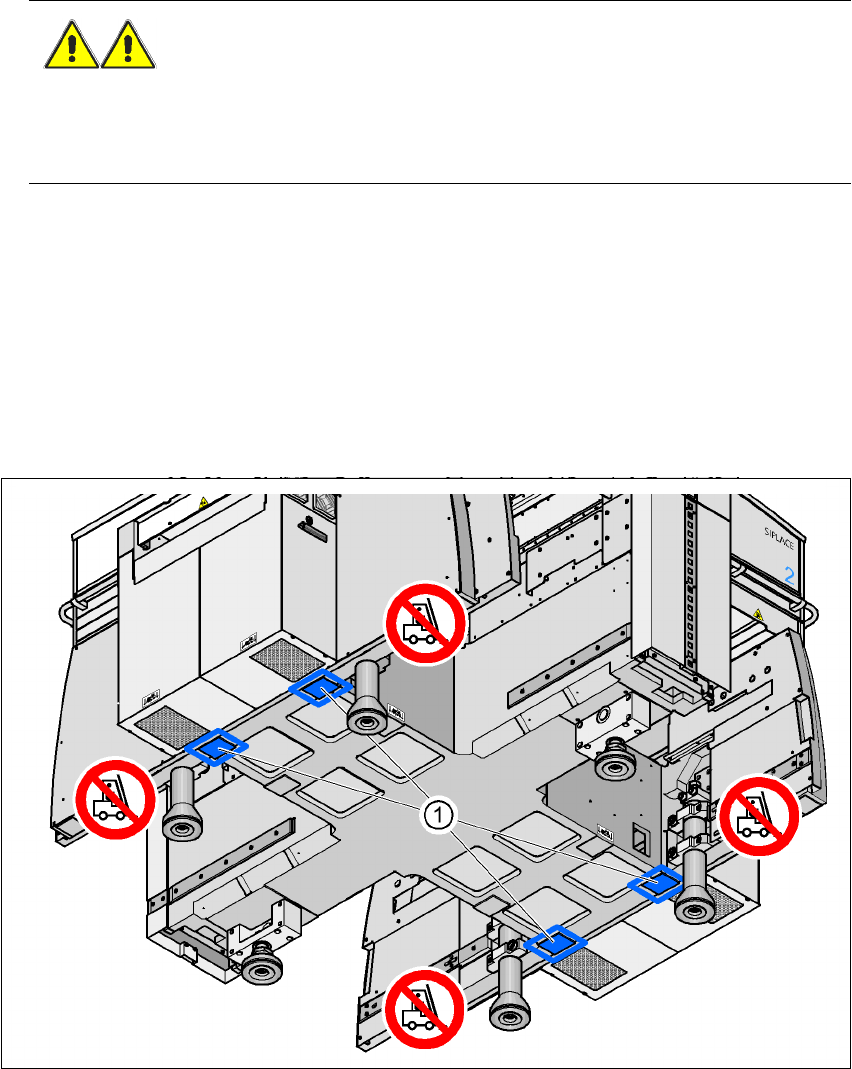
4.5.14.4 Aligning the placement machine with the air cushion transport system
Æ Place the four air cushions of the air cushion transport system beneath the machine frame.
Æ Raise the placement machine and align it with respect to the line.
Æ Check the distance from the PCB conveyor system of the adjacent machine. It should be be-
tween 1 mm and 3 mm.
Æ Lower the placement machine.
4
Fig. 4.5 - 20 Contact positions for the air cushion transport system
(1) Contact surfaces for the air cushion transport system
4 Setting up and commissioning User Manual SIPLACE HF Series
4.5 Setting up the placement machine Software Version SR.505.xx 05/2004 US Edition
200
4.5.15 Making final adjustments to the placement machine
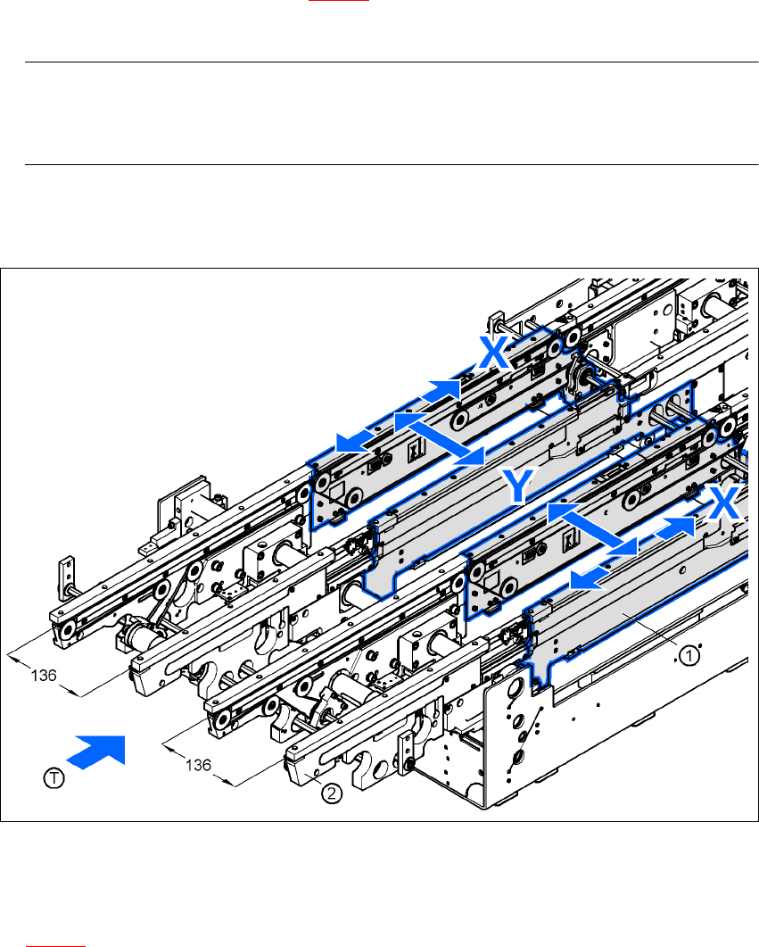
Æ Place the machine's spirit level on the panels of the PCB conveyor in placement area 1 in both
the X and the Y directions (see Fig. 4.5 - 21
). The PCB conveyor width is set to 136 mm by
default.
PLEASE NOTE: 4
On the dual conveyor, place the spirit level only on the outer panels of the machine for ad-
justing in the X direction.
Æ Measure the distance between the top edge of the PCB conveyor and the floor. This distance
should be 800 mm, 900 mm, 930 mm or 950 mm.
4
Fig. 4.5 - 21 Adjusting the placement machine in the X and Y directions
4
4
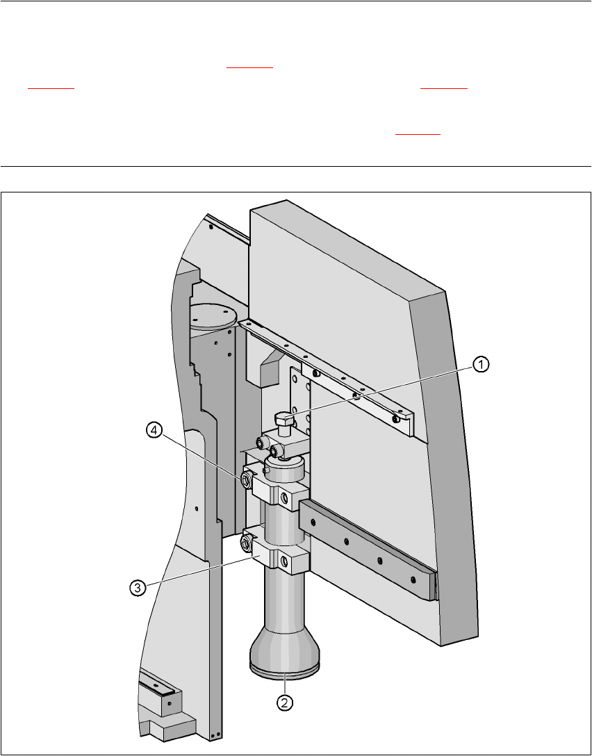
Æ Use the size open-ended spanner to adjust the hexagon head screw M24x80 (item 1 in Fig.
4.5 - 22
) so that the label on the machine spirit level does not deviate from the zero point for
the requested PCB transport height.
User Manual SIPLACE HF Series 4 Setting up and commissioning
Software Version SR.505.xx 05/2004 US Edition 4.5 Setting up the placement machine
201
NOTE
If the machine is set to a PCB transport height of 830 mm and the component trolley docking unit
is fitted in the front position (see Fig. 4.5 - 24
), then the hexagon head screw M24 x 80 (item 1 in
Fig. 4.5 - 24
) is covered by the cylinder air connection (item 3 in Fig. 4.5 - 24) for the component
trolley docking unit.
Æ You should therefore remove the air connection (item 4 in Fig. 4.5 - 24) in order to carry out the
adjustment.
4
Fig. 4.5 - 22 Adjusting the height of the machine feet
(1) Hexagon head screw M24x80 for adjusting the height
(2) Machine foot
(3) Clamp