00193922-01.pdf - 第228页
5 Tasks on the machine User Manual SIPLACE HF Series 5.9 Docking the component trolley in or out Software Version SR.505.xx 05/ 2004 US Edition 228 5.9.4 Docking in the component trolley CAU TIO N Check tha t the plac em…
User Manual SIPLACE HF Series 5 Tasks on the machine
Software Version SR.505.xx 05/2004 US Edition 5.9 Docking the component trolley in or out
227
Æ Press the button on the top of the hand guard (item 1) until the component trolley is docked out.
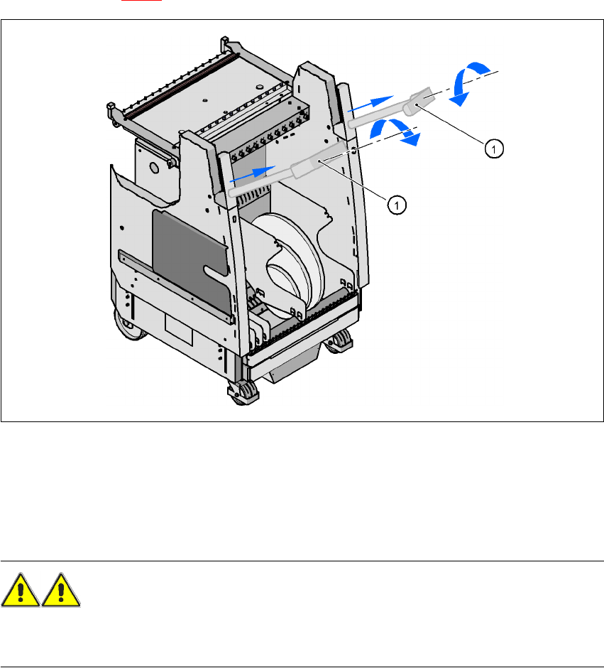
Æ Pull out both transport handles (item 1) on the component trolley, and swivel the handles in-
wards (see Fig. 5.9 - 3
). The handles are then locked in place.
5
Fig. 5.9 - 3 Component trolley - Pulling out the push handles
Æ With both hands on the handles, pull the component trolley out of the placement machine.
5.9.3 Safety instructions for moving the component trolley
WARNING
To prevent accidents, ALWAYS follow the rules listed below when you move the component trol-
ley.
Æ Always hold the handles with both hands when you want to move the component trolley.
Æ Remember that a component trolley with the full complement of feeders can tip over sideways
or forward on gradients of 20° or more.
Æ Make sure that the surface on which the trolley is moved has a significantly smaller gradient.
Æ Be careful not to collide with obstacles. The trolley could tip forward if it is traveling fast enough.
5 Tasks on the machine User Manual SIPLACE HF Series
5.9 Docking the component trolley in or out Software Version SR.505.xx 05/2004 US Edition
228
5.9.4 Docking in the component trolley
CAUTION
Check that the placement head is outside the range of the component trolley.
Æ Press the two buttons on the hand guard at the same time (items 1 and 2 in Fig. 5.9 - 2, page
226
) until the trolley is fully docked in.
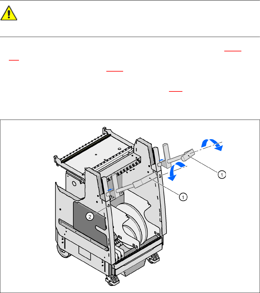
Æ Swivel the handles up (item 1 in Fig. 5.9 - 3) and allow the handles to slide into the component
trolley. They will first engage approximately 6 cm before the end position.
Æ Release the lock by pressing the push-button (item 2 in Fig. 5.9.3). The handles will then slide
into their end position.
Æ Close the protective cover.
5
Fig. 5.9 - 4 Component trolley - Sliding in the handles
(1) Turn the handles
(2) Release the lock
User Manual SIPLACE HF Series 5 Tasks on the machine
Software Version SR.505.xx 05/2004 US Edition 5.10 Note operating status indicator lamp
229
5.10 Note operating status indicator lamp
The indicator lamp is used to signal operating statuses and malfunctions of the placement system.
5.10.1 Description of the functions
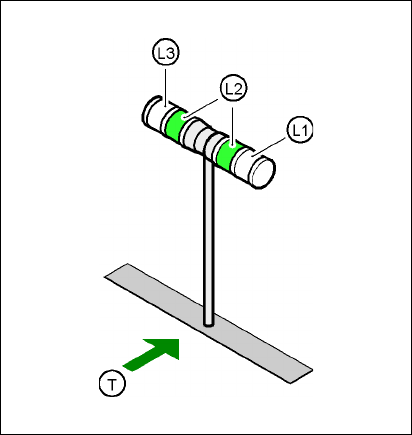
Fig. 5.10 - 1 Operating status indicator lamp
L1 Fault indicator lamp (white, right)
L2 Operating status lamp (green, both lamps switched in parallel)
L3 Fault indicator lamp (white, left)
T Direction of PCB transport
5.10.2 General operating statuses
–
Operating status lamp (green) on continuously
The placement system is in service.
–
Operating status lamp (green) flashes
The placement system is waiting for a PCB on the input belt or the placement system is waiting
until the output belt is free.
–
Right white fault indicator lamp L1 flashes
One or more tracks are empty on the right-hand side of the placement system. The placement
system continues to place any remaining components.