PPS Pro version 8.2.pdf - 第124页
User Manual 4022 591 98247 120 PPS-Pro v8.2 05.07 Guidelines for using PPS-Pro position, then left-click mou se so the soft ware wi ll s ca n/ se a rch for f id ic i als in the artwork that corr espond t o the MDF data. …
4022 591 98247 User Manual
05.07 PPS-Pro v8.2 119
Guidelines for using PPS-Pro
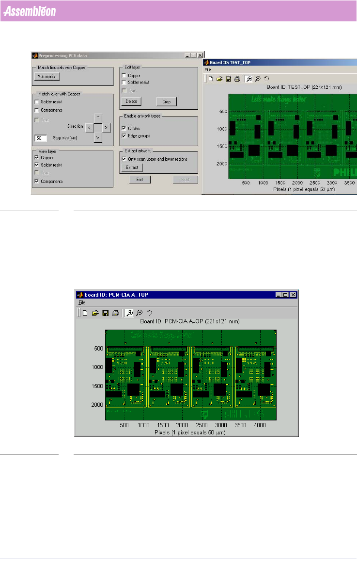
SCREEN 69 Step2 Aligning artwork with Cad data
This step is to align the MDF data with the Artwork data from the Gerber files.
The MDF data and the PSI information is used to obtain the correct size of the
components on the board. These will be shown as black boxes in the graphical
presentation
(see SCREEN 70 "Unaligned Artwork with Cad data" on page
119).
SCREEN 70 Unaligned Artwork with Cad data
The first action in this stage is to use the “Automatic”-button. After pressing
the “Automatic”-button in the “Preprocessing PCB data”-window a new
window pops up
(see SCREEN 72 "Aligned Artwork with board data" on page
121). By shifting the mouse until the circle with cross is on the correct
fiducial (see SCREEN 71 "Matching gerber with fiducial after alignment" on
page 120) and automatically all components (black boxes) are on the correct
User Manual 4022 591 98247
120 PPS-Pro v8.2 05.07
Guidelines for using PPS-Pro
position, then left-click mouse so the software will scan/search for fidicials in
the artwork that correspond to the MDF data.
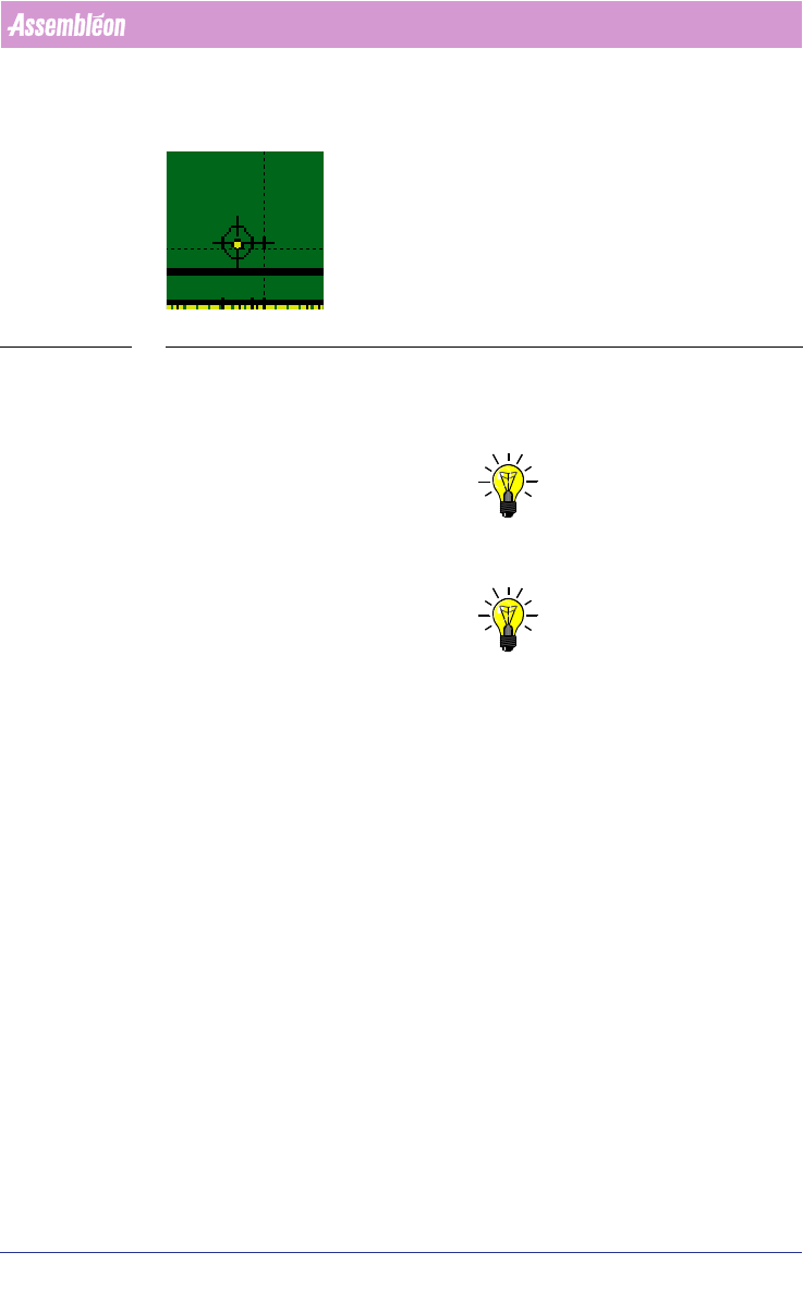
SCREEN 71 Matching gerber with fiducial after alignment
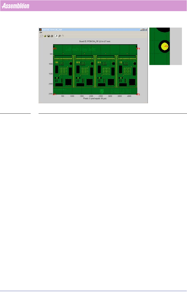
After the window is closed and the fiducials are presented in the graphical
presentation by displaying these as a red cross and fiducial name. Zoom in on
a fiducial to check whether it is found correctly
(see SCREEN 72 on page 121).
NOTE: To zoom in simple click in the area where to zoom or draw with a mouse click
a rectangle on the location that must be zoomed in.
NOTE: Sometimes it looks like the fiducials are not located exactly at the correct
place. But by zooming in on the fiducial, the red cross should come close to
the centre of the fiducial.
If the fiducials are not correctly found repeat the process (Use the
“Automatic”-button). Most often in that situation it is possible to resolve by
repeating the action (matching the standard fiducials of the CAD (MDF) and
the Gerber data).
4022 591 98247 User Manual
05.07 PPS-Pro v8.2 121
Guidelines for using PPS-Pro
SCREEN 72 Aligned Artwork with board data
3.3.4.5 Preprocessing PCB data
Other options in the “Preprocessing PCB data”-window are: (see SCREEN 69
"Step2 Aligning artwork with Cad data" on page 119)
1. “Match fiducial with Copper”-frame: By activating the button “Automatic”
the matching between the MDF data and the Gerber data can be
performed.
2. “Match layer with Copper”-frame: By ticking and un-ticking, solder resist
layer can be shifted by using the “^v<>”-buttons. With these buttons the
selected layers can be shifted by the step size (in um)
3. “Edit layer”-frame: By ticking and un-ticking copper layer, solder resist
layer can be selected for deletion.
a) Delete:The deletion can be done via the “delete”-button.
b) Crop”: With this button the selected layers can be cropped.
Example: If the Gerber data also contains a frame or other non-
relevant data out-side of the PCB data, this can be cleaned.
4. Enable artwork types: When the AX doesn’t recognize the genetrated
Artwork it is possible to disable certain kind of Artworks
5. “Extract artwork”: (Note, this is currently not automatic) This will start
the artwork extraction. This will take some minutes. A progress bar is
shown and the “Next”-button is enabled
a) Only scan upper and lower regions: When there is not sufficient
Artwork in the upper and lower regions this option can be used
for extracting artwork in the middle of the board