PPS Pro version 8.2.pdf - 第169页
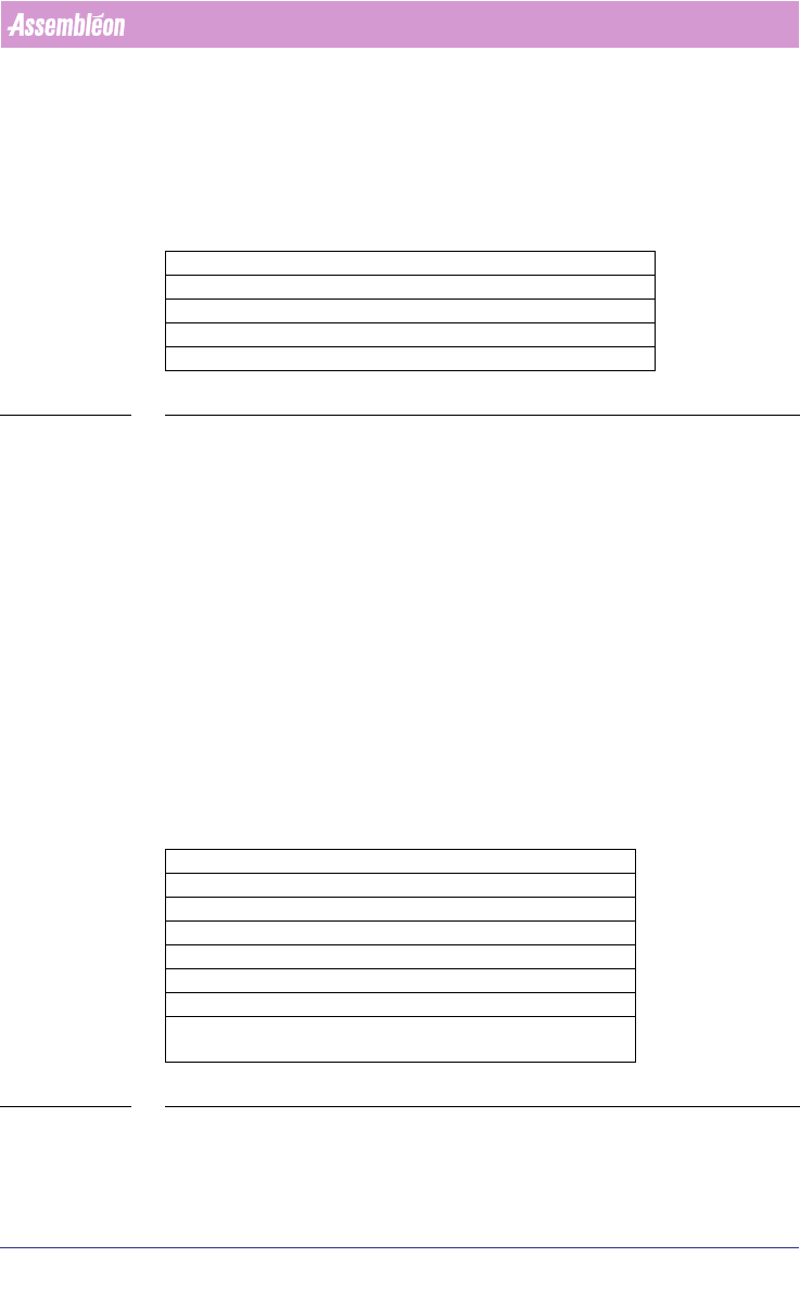
4022 591 98 247 U ser Manual 05.07 P PS-Pro v8.2 165 Guidelines for using PPS-Pro Fo r t h e FCM-IIM and FCM-IIXM and a dditional set o f param eters can be ch a nged by t he use r: T ABLE 31 ALE Settings Attribut es for…
User Manual 4022 591 98247
164 PPS-Pro v8.2 05.07
Guidelines for using PPS-Pro
A.6.3.2 AX Index Schemes
For the AX type machines, the optimizer will calculate the required index
scheme (transport index settings). However, a user can override this by
defining his own required index schema.
For AX machines, following parameters can be modified:
TABLE 29 ALE Settings Attributes for AX
For the conveyor settings there are 3 possible options:
■ Auto mode
■ Semi-Auto mode
■ Manual mode
Normally use Auto mode. This means that NONE of following AX machine
production parameters are entered in the ALE file: TransportStopperInX,
TransportNrOfBoards, TransportIndexStep, TransportPanelPitch.
There might be situations you want to use Semi-Auto or Manual mode. This is
however not advised! For Semi-Auto the production parameters Transport
-
StopperInX and TransportPanelPitch must be specified in ALE. For Manual-
Auto the production parameters TransportStopperInX, TransportNrOf
-
Boards, and TransportIndexStep must be specified in ALE.
A.6.3.3 FCM-II – FCM-IIM – FCM-IIXM Production Parameters
For these machines the following parameters can be changed:
TABLE 30 ALE Settings Attributes for FCM-II, FCM-IIM and FCM-IIXM
The Mark parameters refer to the used shape definition file (vision file) on the
FCM machines.
Index Scheme Parameter AX
TransportStopperInX e.g. 0.036 (unit is meters!)
TransportNrOfBoards e.g. 24
TransportIndexStep e.g. 0 0.12 (unit is meters!)
TransportPanelPitch e.g. 0.12 0.12 (unit is meters!)
Parameter FCM-II - FCM-IIM - FCM-IIXM
BoardVision BMS+DFA or BMS or DFA or NO
BVM1Index YES or NO
PanelFidMark <number 1 – 255> e.g.: 1
BoardFidMark <number 1 – 255> e.g.: 2
PanelBadMark <number 1 – 255> e.g.: 3
BoardBadMark <number 1 – 255> e.g.: 4
VisionPosition 1 or 2 or 3 - For a WPM head this param-
eter has to be defined
4022 591 98247 User Manual
05.07 PPS-Pro v8.2 165
Guidelines for using PPS-Pro
For the FCM-IIM and FCM-IIXM and additional set of parameters can be
changed by the user:
TABLE 31 ALE Settings Attributes for FCM-IIM & FCM-IIXM
NOTE: When DEFAULT is defined, the optimizer calculates the Reference Points. The
user can overrule this by defining these coordinates himself.
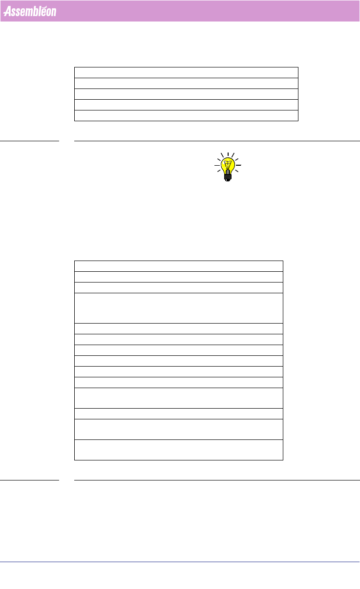
A.6.3.4 AX machine Production Parameters
For the AX base3 and base5 machines, following important parameters are
user definable:
TABLE 32 ALE Settings Attributes for AX
The LogicalPositionInLine defines the place of the machine in the line. Thus, if
an SMD line exists of AX machine – AX machine – AQ-1 machine, then the
logical position of the first AX machine is 1, of the second one is 2 and for the
Parameter FCM-IIM - FCM-IIXM
RightReferencePin DEFAULT or <value> e.g.: 123.45
LeftReferencePin DEFAULT or <value> e.g.: -34.29
BadMarkGrouping ON or OFF
FiducialGrouping ON or OFF
Parameter AX
BaseType BASE_3 or BASE_5
ProductionMode LOCAL or DISTRIBUTED
PanelFidMark
BoardFidMark
PartFidMark
<user definable> identifi-
ers for Panel, Circuit and
Part fiducials
BadMarkId <user definable>
LogicalPositionInLine 1 or 2 or 3 etc.
ProcessDataVersion 1.0
ControlSoftwareVersion 1.0
DoNotDuplicatePreassignment TRUE or FALSE
AlignmentMatrixPerCircuit TRUE or FALSE
MaxNoFiducialsPerAlignment-
Matrix
2 or 3
BadMarksRequireFiducials TRUE or FALSE
EnableNeighborhoodRestric-
tions
TRUE or FALSE
ProductionDirection RIGHT_TO_LEFT or
LEFT_TO_RIGHT

User Manual 4022 591 98247
166 PPS-Pro v8.2 05.07
Guidelines for using PPS-Pro
third 3. This information is used when parts have to be placed last, these are
transferred to the machine with the highest LogicalPositionInLine.
PanelFidMark, BoardFidMark, PartFidMark fields: When the used fiducials,
either in LAR- or DSF ProductionMode have no name assigned, then this user
definable name will be used in the Placement Program. This name refers to
the used shape definition file (vision file) on the AX machines.
BadMarkId field: Specifies the name that has been assigned in the MDF file
(CAD) file for the badmark.
The DoNotDuplicatePreassignments field: When preassigned parts are not
allowed to be duplicated this option can be used. Note that parts in the PCB
should be reachable (and the fiducials should be read in advance), otherwise
this option should be turned off.
The AlignmentMatrixPerCircuit field: Only the fiducials in the circuit itself may
be used for alignment of the parts in the circuit. (Important when carriers are
used.)
The MaximumNoFiducialsPerAlignmentMatrix field: This field defines the
number of fiducials that will be scanned per Alignment Matrix.
The BadmarksRequireFiducials field: This field specifies if it is mandatory to
first read fiducials before badmarks can be read, or not. (Practical situation is
circuit carriers without fiducials.)
The EnableNeighborhoodRestrictions field: This field specifies if the optimizer
for AX machines has to take care that the placement of smaller parts next to
larger parts can cause the nozzle shaft to displace the larger parts. By turning
on this function the optimizer will generate programs where the larger parts
will be placed after the small parts that are nearby have been placed.
The ProductionDirection field: Can only be used if special hardware modifi-
cations have been done on the machine in order to allow PCB transport in
reverse direction.
NOTE: See for the other parameters the ALE Description.
A.6.3.5 ACM, AQ-1 and D9 Production Parameters
For these machines the following parameters can be set:
Parameter ACM – AQ-1, AQ-2 – D9
ModulePosition1 FLUX or TEU
ModulePosition2 CSP, FP (AQ1)
or
DV_SFOV, DV_LFOV (AQ2)