PPS Pro version 8.2.pdf - 第173页
4022 591 98 247 U ser Manual 05.07 P PS-Pro v8.2 169 Guidelines for using PPS-Pro APPENDIX B Gerber Files B .1 What is Gerber Data? Man y people hav e difficulty ev al uating an d usin g Gerber processing so ftware becau…
User Manual 4022 591 98247
168 PPS-Pro v8.2 05.07
Guidelines for using PPS-Pro
A.6.3.6 ACM, D9, AQ-1 and AQ-2 Tray Definitions
A user can define his own trays, including name and all required dimensions.
These new user trays should then be selectable on the required Tray-pallets.
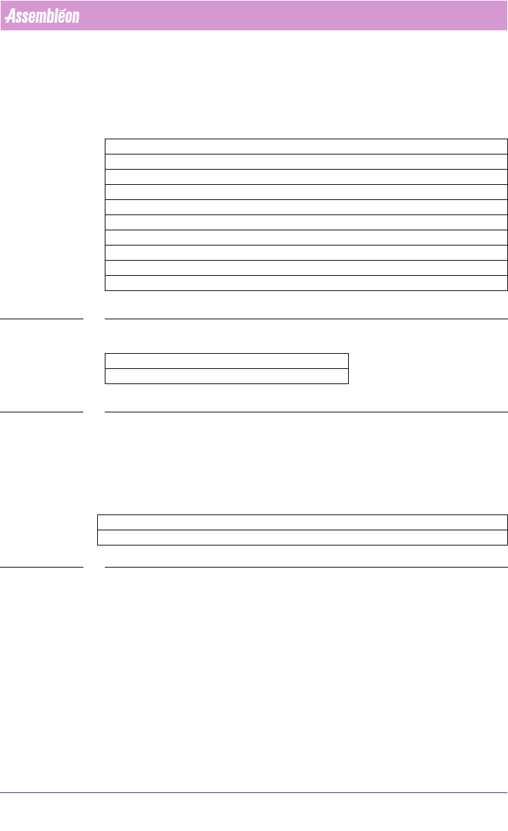
The following parameters define a Tray:
TABLE 34 ALE Settings Tray for ACM, AQ-1, D9
For the AQ-1, the following parameter can be set:
TABLE 35 ALE settings AQ-1, AQ-2
Refer to AX machine Production Parameters for an explanation regarding this
parameter.
A.6.3.7 Optimizer Names
The following is a list of Assembléon optimizer names.
TABLE 36 Machine Optimizer to be used
Parameter ACM – AQ-1 – D9 Definable TRAYS
XDimension X-size of tray, e.g.: 135.9
YDimension Y-size of tray, e.g.: 322.6
ZDimension Z-size of tray, e.g.: 12.19
XPick X-Center location first part in tray, e.g.: 17.7
YPick Y-Center location first part in tray, e.g.: -22.7
XNr Number of ‘cells’, e.g.: 5
YNr Number of ‘Rows’, e.g.: 11
XPitch X-distance between 2 ‘Cells’, e.g.: 25.1
YPitch X-distance between 2 ‘Rows’, e.g.: 27.7
Parameter AQ-1, AQ-2
LogicalPositionInLine 1 or 2 or 3 etc
Parameter FCM-II FCM-IIM FCM-IIXM ACM D9 AQ-1, AQ-2 AX
OptimizerName Emt_mod.exe AssembleonOptimizer.bat

4022 591 98247 User Manual
05.07 PPS-Pro v8.2 169
Guidelines for using PPS-Pro
APPENDIX B Gerber Files
B.1 What is Gerber Data?
Many people have difficulty evaluating and using Gerber processing software
because it is difficult to see how it relates to “CAD data”.
Gerber data is an old data format (in the electronics assembly calendar) that is
used to operate photo plotters. Photo plotters create the patterns of bare
boards and therefore the data used to drive the plotter is the closest represen
-
tation of the actual product available. Conversely, people not involved in
assembly develop CAD data during board design. The X, Y positions of
components are defined by part libraries in the CAD system that may not match
the centroid that the manufacturing engineer needs for the placement or
insertion system. This CAD data is then used to generate the Gerber files in an
additional step. There are often differences between ASCII CAD positional data
and Gerber data due to the CAD system’s design as well as the conversion
process to Gerber.
Furthermore, if the board fabricator makes changes to the Gerber file for manu-
facturability reasons, the CAD data is then useless. Gerber data is also generally
available since it must be used to fabricate the board, and the data is stand
-
ardized unlike the myriad of different CAD formats on the market. For a manu-
facturer receiving boards from many different customers with different CAD
systems, the cost of several interfaces and the training involved in different
formats can be prohibitively expensive. Don’t worry about software revision.
changes to data formats— Gerber data is a universally employed format and is
here to stay! In general, it is the most accurate, most available, and only truly
standardized board data!
B.2 The Downside of Gerber Data
Because the Gerber format is so old, the previous version
(274D)
is plagued by
a need for what is called an
“aperture list.”
To understand aperture lists,
consider a pen plotter, which is very similar to the older photo plotting
equipment. The pen needs to be moved about the paper and the plotter must be
told which pen to use at all times. Original photo plotters used light shined
through “apertures” to project the board patterns. The aperture list is a file
separate from the Gerber files and defines the apertures used by the CAD
engineer’s system when the file was generated. This sounds simple enough—
except that there is no standard for aperture list formatting and they are often
difficult to import for use by a Gerber digitizing system.
The Gerber format
(274X)
eliminates the need for aperture lists and is
becoming more common. Gerber data consists only of graphics. There is no data
storage of part information, rotation, or designator. Also, until recently there
was no way to easily extract the pad or through-hole groupings of each
component due to the graphics-only nature of the data. Systems required that
the user maintain and develop “libraries” of standard pad groupings of

User Manual 4022 591 98247
170 PPS-Pro v8.2 05.07
Guidelines for using PPS-Pro
components that the system would search for in the Gerber file. However,
standard pad layout designs often change and many designers customize their
pad groupings for various reasons, rendering these libraries useless. The
operator then needs to “teach” the new groupings. As you can imagine, this
becomes a time intensive and aggravating task for the operator of the appli
-
cation. Finally, until recently, the fastest means of extracting reference desig-
nators from the file was a text recognition system that looks for text of a
certain size and then joins it to the closest part on the board. This process
takes a very long time and is not always reliable. As anyone who works with
boards knows, the reference designators are often difficult to associate with
component locations on dense assemblies— imagine how hard it is for a
computer lacking intuition! Also imagine how hard it is to find the errors the
computer made on a 400-component board! You might as well enter the data
manually in the first place. Finally, present digitizers cannot process layers
with traces on them and need special, time-consuming manipulation of rastered
pads.
(See definition below)
B.3 What is a rastered pad?
Pads are often drawn as a single “flash” in Gerber files. However, as technology
changes, more files are using “rastered pads.” Each pad can be constructed of
many lines (40-60) drawn in a zigzag fashion to fill in the pad area. In order for
most Gerber digitizers to accept this type of pad, extra manual manipulation is
needed on each component to change the pads into flashes! This is a time-
consuming step on your way to a digitized assembly.