PPS Pro version 8.2.pdf - 第60页
User Manual 4022 591 98247 56 PPS-Pro v8.2 05.07 PPS-Pr o GUI SCREEN 34 Fid uci al with Arrang emen t 4. De-select (Ctrl d) an d repeat step 2 an d step 3 until all groups hav e been created. 2.19 Set Badmark Grouping Th…
4022 591 98247 User Manual
05.07 PPS-Pro v8.2 55
PPS-Pro GUI
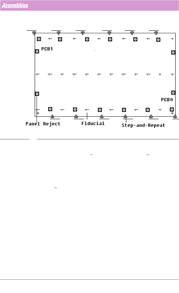
SCREEN 33 Fiducial without Arrangement
To set a fiducial arrangement, follow these steps:
1. In the MDF editor, click File > Group Mode. Now the Groups menu bar
can be viewed.
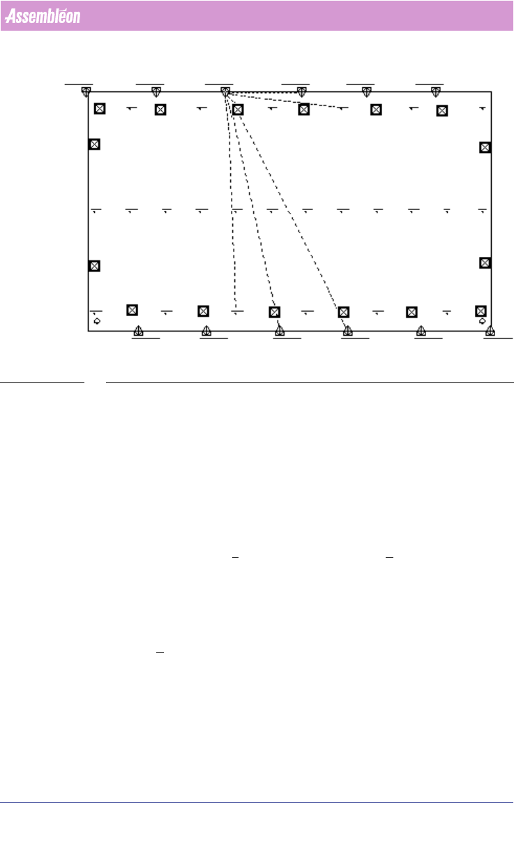
2. For example, select four step-and-repeat symbols and two fiducials by
clicking on the corresponding symbol in MDF. Notice color of the selected
symbols turns to purple. Take care that the fiducials must belong to the
circuits that relate to the step-and-repeat symbols.
3. Click Groups > Create New Group. Now a fiducial arrangement is created
by grouping the four step-and-repeat with only two fiducials. This fiducial
arrangement is shown with a white dotted line connecting step-and-
repeats and fiducials symbols
(see SCREEN 34 on page 56).
User Manual 4022 591 98247
56 PPS-Pro v8.2 05.07
PPS-Pro GUI
SCREEN 34 Fiducial with Arrangement
4. De-select (Ctrl d) and repeat step 2 and step 3 until all groups have been
created.
2.19 Set Badmark Grouping
The following paragraph describes how to set the badmark grouping using the
MDF editor. This is to set the badmark on panel level so that any number of
circuits can be set to one badmark by grouping.
To set the badmark grouping, follow the steps explained below:
1. In MDF editor, click File > Group Mode. Now the Groups menu bar can be
viewed.
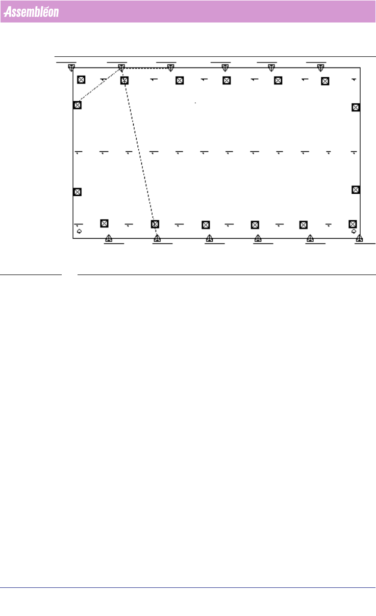
2. For example, select three step-and-repeat symbols and one panel badmark
by clicking on the corresponding symbol in MDF. Notice the color of the
selected symbols turns to purple. Take care that the panel badmark must
belong to the circuits that relate to the step-and-repeat symbols.
3. Click Groups > Create New Group. Now a badmark group is created by
setting three step-and-repeat with one panel badmark. Badmark grouping
is shown with green dotted line connecting step-and-repeats and panel
badmark symbols
(see SCREEN 35 on page 57).
4. De-select (Ctrl d) and repeat the step 2 and step 3 until all groups have
been created.
4022 591 98247 User Manual
05.07 PPS-Pro v8.2 57
PPS-Pro GUI
SCREEN 35 Badmark Grouping
2.20 Area Badmarks (A-Series)
With this functionality the concept of Master badmarks (Multiple Level) is
also supported for AX software version 1.11 or later.
2.20.1 Area badmark support on A-Series machines
This feature is always used in combination with badmark groups. There are
three types of badmarks available:
1. circuit badmarks
2. area badmarks
3. panel badmarks
The following picture shows a PCB that contains these three types. On this
PCB groups are used to relate circuit badmarks to area badmarks.