00191297-02.pdf - 第100页
3 Introduction and Ba sic Concepts User Manual SIPLACE S-23 HM 3.2 Principles of the Graphic User I nterface Software Version SR.405.xx 05/99 I ssue 98 3.2.2.2 T oolbar in Main View 3 Fig. 3.2 - 2 T oolbar in main view 3…
User Manual SIPLACE S-23 HM 3 Introduction and Basic Concepts
Software Version SR.405.xx 05/99 Issue 3.2 Principles of the Graphic User Interface
97
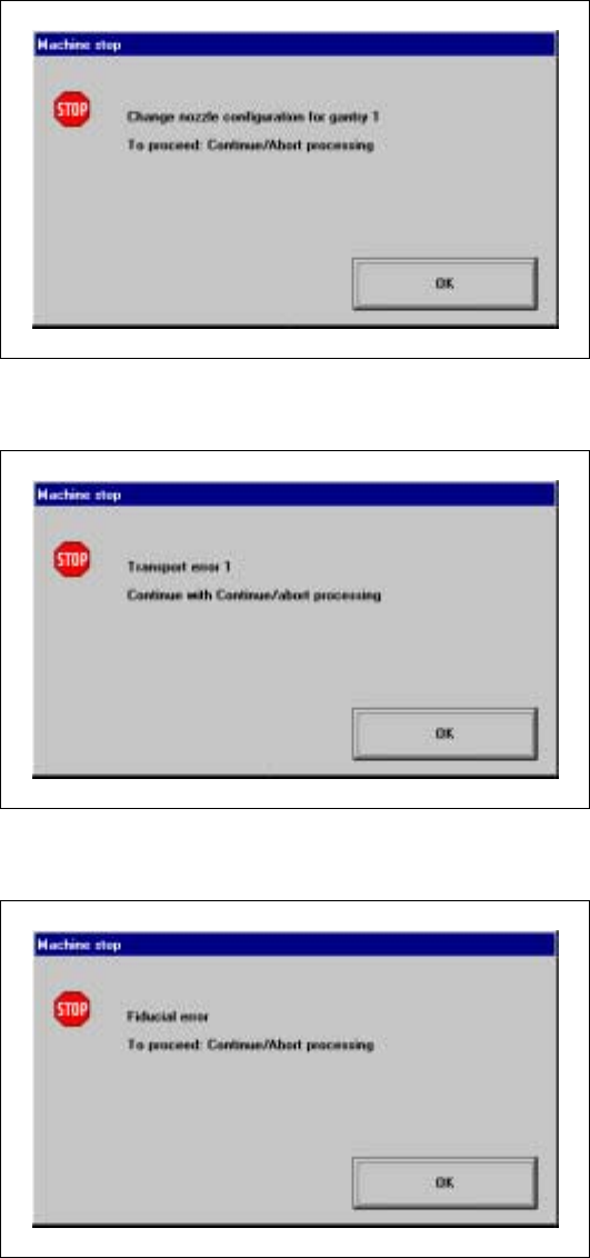
Nozzle configuration error 3
3
3
Transport error 1 3
3
3
Fiducial error 3
3
3
3
3
3
3
3
3
3
3 Introduction and Basic Concepts User Manual SIPLACE S-23 HM
3.2 Principles of the Graphic User Interface Software Version SR.405.xx 05/99 Issue
98
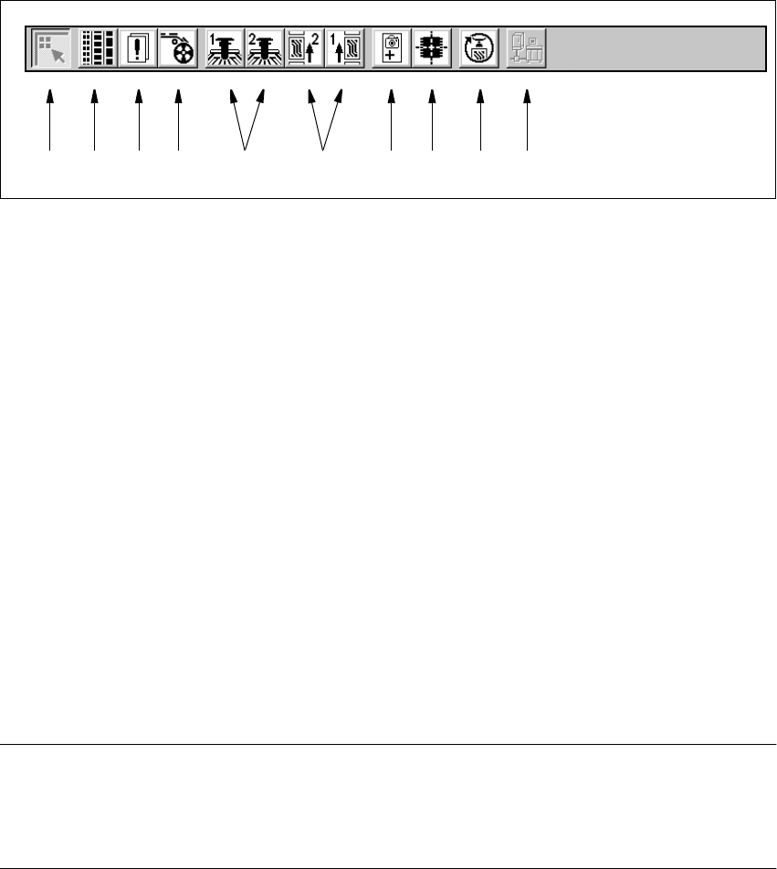
3.2.2.2 Toolbar in Main View
3
Fig. 3.2 - 2 Toolbar in main view
3
Key to Figure 3.2 - 2
(1) Main view
(2) Set-up, placement functions (for a description see Chapter 4)
(3) Error, placement functions (for a description see Chapter 4)
(4) Component feeder, placement functions(for a description see Chapter 4)
(5) Gantry 1 to 2, single functions (for a description see Chapter 5)
(6) Conveyor 1 and 2, single functions (for a description see Chapter 5)
(7) Teach fiducials, vision functions (for a description see Chapter 6)
(8) Test component, vision functions (for a description see Chapter 6)
(9) Start SITEST test program (for a description see User’s Manual
"Test Program SITEST")
(10) GEM interface (for a description see Chapter 12)
3
NOTES to points 6 and 10
The single functions for Conveyor 2 can only be called if a twin conveyor has been configured.
The GEM interface functions cannot be called unless this has been configured.
The "GEM Interface" option cannot be configured in the current software version. 3
È Click the required button in the toolbar.
The user interface is switched to the corresponding view.
The button corresponding to the view which is currently active itself becomes inactive.
3
1 8 9 1076432 5
User Manual SIPLACE S-23 HM 3 Introduction and Basic Concepts
Software Version SR.405.xx 05/99 Issue 3.3 User Interface - Views and Menus
99
3.3 User Interface - Views and Menus
3.3.1 Views
To perform a particular operation at a particular moment via the user interface, you may need to
switch this to a different view. You can do this by clicking the appropriate toolbar button (see
section 3.2.2.2) or by selecting the corresponding menu item in the "View" menu (see section
3.3.2.2). 3
NOTE
For a description of the functions available in the various views, refer to the chapters which explain
the procedures applicable to the operations to be performed (e.g. "Refilling Empty Tracks",
Chapter 4). 3
3.3.2 Menus
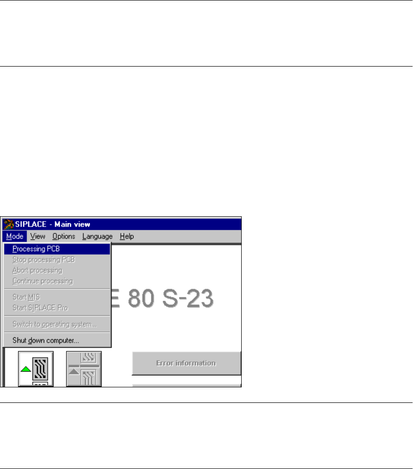
3.3.2.1 "Mode" Menu
The complete set of functions present in the "Mode" menu is only available in the main view.
In the views "Setup ...", "Errors..." and "Feeders" and their sub-views, only the menu items "Stop
processing PCB" and "Processing PCB" are available. In the other views, the "Mode" menu is not
displayed. 3
3
NOTE
For a detailed description of the menu items "Stop processing PCB", "Processing PCB" and
"Continue processing", refer to section 3.2.2.1 since these functions are usually activated via the
corresponding icons in the working area. 3