00191297-02.pdf - 第23页
User Manual S-23 HM 1 Introduction Software Vers ion SR.405.xx 05/99 Issue 1.5 Description of the machine 21 1.5 Description of the machine 1.5.1 Functional description The automati c place ment sys tem is a high-pe rfor…

1 Introduction User Manual S-23 HM
1.4 Revision index Software Version SR.405.xx 05/99 Issue
20
PLEASE NOTE: The content of this User Manual is not part of or intended to modify a previous or
existing agreement, undertaking or legal relationship. Any undertakings entered into by Siemens
AG result from the purchase contract, which also contains complete and generally applicable
guarantees. Such contractual guarantee provisions are neither extended nor restricted by the in-
formation given in this User Manual. 1
1.4 Revision index
Manual Software version Issue
First draft S-23 HM Provisional User Manual 405 01/99
Revision S-23 HM User Manual 405 05/99
User Manual S-23 HM 1 Introduction
Software Version SR.405.xx 05/99 Issue 1.5 Description of the machine
21
1.5 Description of the machine
1.5.1 Functional description
The automatic placement system is a high-performance placement system with two gantry axis
systems. A PCB vision system and a star-shaped 12-segment revolver head are mounted on each
gantry. Revolver placement heads equipped with a component vision system pick up the compo-
nents from stationary feeder modules and place them onto the PCB clamped in the PCB conveyor.1
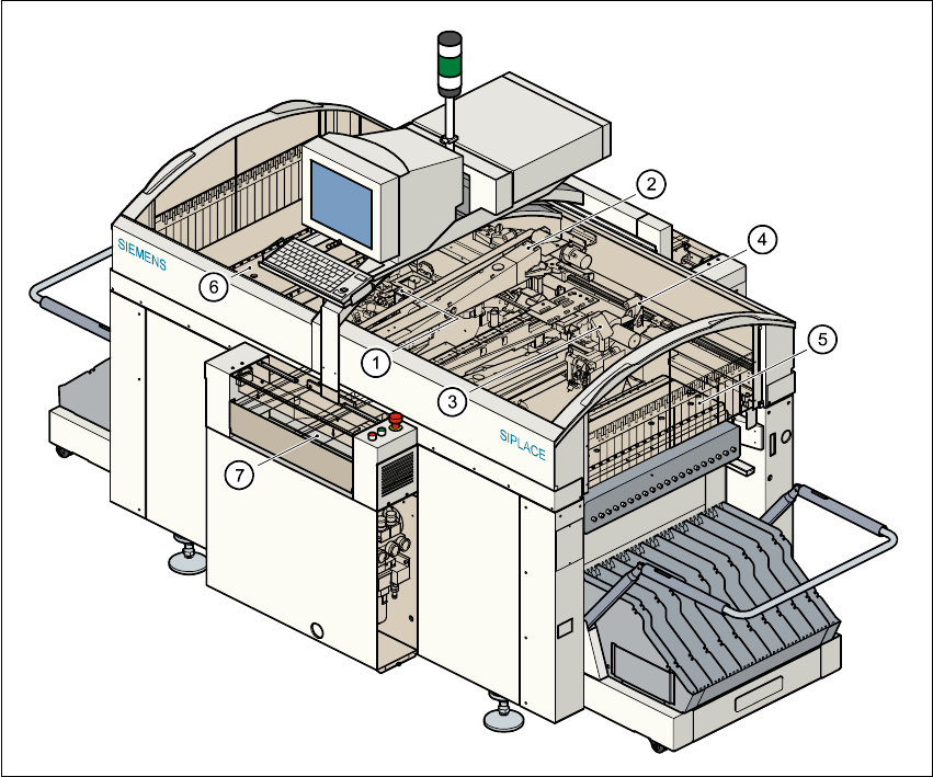
Fig. 1.5 - 1 Functional description of the placement system
(1) 12-segment revolver head /DLM1 with component vision camera (gantry 1)
(2) Gantry 1 with component vision camera
(3) 12-nozzle revolver head /DLM1 with component vision camera (gantry 2)
(4) Gantry 2 with PCB vision camera
(5) Stationary component supply (location 1)
(6) Stationary component supply (location 3)
(7) PCB conveyor (dual conveyor option)

1 Introduction User Manual S-23 HM
1.5 Description of the machine Software Version SR.405.xx 05/99 Issue
22
The concept behind the automatic placement system 1
– with its stationary feeder modules,
– PCBs that do not move during placement
– and positionable placement heads
has a number of significant benefits: 1
– For example, the flexible 12-segment revolver heads combined with automatic nozzle chang-
ers enable the nozzle configuration to be changed temporarily and automatically adapted to
receive different component sizes. You can also optimize the traversing paths and the place-
ment sequence.
– With stationary feeder modules, even the tiniest components are picked up reliably.
– The components cannot slip on the PCB during placement (as is often the case with moving
PCBs) since the PCB does not move.
– Sophisticated optical centering systems (vision systems) for components and PCBs also en-
sure high component positioning accuracy.
– Components can be topped up and tapes can be spliced without stopping the machine.
– Prepared component tables enable the placement system to be retooled without long stop-
pages.
1.5.2 Head Modularity concept (HM)
The abbreviation HM in the designation of the SIPLACE S-23 HM placement system stands for
Head Modularity. 1
The aim of this concept is to allow any combination of 6-nozzle and 12-nozzle revolver heads to
be used on the placement system. A simple head change procedure will enable the system to
be quickly adapted to the requirements of individual placement jobs. 1
The head modularity concept will be implemented in the next development stage. Placement sys-
tems supplied with the designation HM are designed to be compatible with the new concept. 1