00191297-02.pdf - 第85页
User Manual S-23 HM 1 Introduction Software Vers ion SR.405.xx 05/99 Issue 1.15 Overview of the m odules - PCB conveyor 45 1.15 Ov erview of the modules - PCB conveyor 1.15.1 Structure of the PCB conveyor The place ment …
2 Operational Safety User Manual S-23 HM
2.8 ESD guidelines Software Version SR.405.xx 05/99 Issue
84
Do not allow modules with chargeable and highly insulating materials to touch one another, e.g.
plastic films, insulating table surfaces or items of clothing made from synthetic fibers. 2
Always place the modules on a conductive surface (table with an ESD coating, conductive ESD
foam, ESD bag or container). 2
Do not bring modules near visual display units, monitors or televisions. Keep them at least 10 cm
away from the screen. 2
2.8.4 Measurements and modifications to ESD modules
Do not take measurements on such modules unless
È the measuring device is earthed (e.g. via PE conductors) or
È you discharge the measuring head just before taking measurements with a potential-free mea-
suring device (e.g. by touching an unpainted metal part of the controller casing).
È Always use an earthed soldering iron if you carry out any soldering work.
2.8.5 Dispatching ESD modules
È Always store modules and components in conductive packaging (e.g. metallized plastic bags
or metal sleeves) and dispatch them in conductive packaging.
If the packaging is not conductive, place the modules in a conductive envelope before pack-
aging. (Use ESD bags, domestic aluminum foil or paper, for example. NEVER use plastic bags
or film). 2
È If the module has integral batteries, ensure that the conductive packaging does not touch or
short-circuit the battery terminals and, if necessary, first cover the terminals with insulating tape
or material.
2
User Manual S-23 HM 1 Introduction
Software Version SR.405.xx 05/99 Issue 1.15 Overview of the modules - PCB conveyor
45
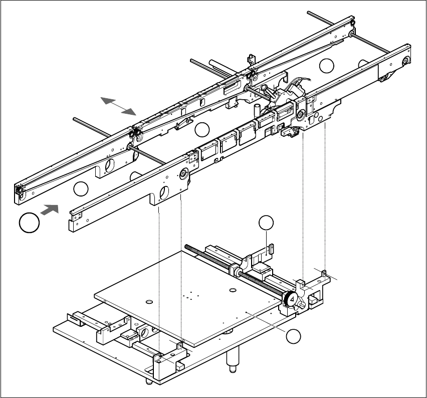
1.15 Overview of the modules - PCB conveyor
1.15.1 Structure of the PCB conveyor
The placement system is supplied with a single conveyor as standard. A dual conveyor is avail-
able as an option. 1
The left or the right side of the PCB conveyor can be used as the stationary side, as required. 1
1
Fig. 1.15 - 1 PCB transport - single conveyor
(1) Input conveyor (2) Center conveyor
(3) Output conveyor (4) Lifting table
(5) Width adjustment T Direction of PCB transport 1
T
4
1
2
3
5

1 Introduction User Manual S-23 HM
1.15 Overview of the modules - PCB conveyor Software Version SR.405.xx 05/99 Issue
46
The conveyor belts are driven by DC motors. The lifting table near the center conveyor clamps the
PCBs in position. The width of the PCB conveyor can be adjusted either 1
– via the menu or
– using the line computer.
1
1.15.2 Technical data - single conveyor
1.15.3 Technical data - dual conveyor
1
PCB format 50 mm x 50 mm to 460 mm x 460 mm
2" x 2" to 18 " x 18 "
Option: upto 508mm x 460mm
upto 20" x 18 "
PCB thickness 0.5 mm to 4.5 mm
Maximum PCB curvature On top: 4.5 mm - PCB thickness
On bottom: 0.5 mm + PCB thickness
Clearance underneath PCB 40 mm
PCB conveyor height 830 ± 15 mm (standard)
Type of interface Siemens (standard)
Clear guide edge of component 3 mm
PCB changeover time 2.5 s
PCB format 50 mm x 50 mm to 460 mm x 216 mm
2" x 2" to 18" x 8.5"
Option: upto 508mm x 216mm
upto 20" x 8,5"
Fixed edge of conveyor Right (standard), left (option)
Placement sequence per conveyor Synchronous: same or different
Asynchronous: same
PCB width per conveyor Synchronous: different
Asynchronous: same
Ink spot recognition Synchronous: not possible
Asynchronous: possible
Automatic width adjustment Synchronous: not possible
Asynchronous: possible