00191297-02.pdf - 第87页
User Manual SIPLACE S-23 HM 3 Introduction and Basic Concepts Software Vers ion SR.405.xx 05/99 Iss ue 85 3 Introduction and Basic Concept s This cha pter desc ribes the machine display s and co ntrols t ogether wi th th…

1 Introduction User Manual S-23 HM
1.15 Overview of the modules - PCB conveyor Software Version SR.405.xx 05/99 Issue
46
The conveyor belts are driven by DC motors. The lifting table near the center conveyor clamps the
PCBs in position. The width of the PCB conveyor can be adjusted either 1
– via the menu or
– using the line computer.
1
1.15.2 Technical data - single conveyor
1.15.3 Technical data - dual conveyor
1
PCB format 50 mm x 50 mm to 460 mm x 460 mm
2" x 2" to 18 " x 18 "
Option: upto 508mm x 460mm
upto 20" x 18 "
PCB thickness 0.5 mm to 4.5 mm
Maximum PCB curvature On top: 4.5 mm - PCB thickness
On bottom: 0.5 mm + PCB thickness
Clearance underneath PCB 40 mm
PCB conveyor height 830 ± 15 mm (standard)
Type of interface Siemens (standard)
Clear guide edge of component 3 mm
PCB changeover time 2.5 s
PCB format 50 mm x 50 mm to 460 mm x 216 mm
2" x 2" to 18" x 8.5"
Option: upto 508mm x 216mm
upto 20" x 8,5"
Fixed edge of conveyor Right (standard), left (option)
Placement sequence per conveyor Synchronous: same or different
Asynchronous: same
PCB width per conveyor Synchronous: different
Asynchronous: same
Ink spot recognition Synchronous: not possible
Asynchronous: possible
Automatic width adjustment Synchronous: not possible
Asynchronous: possible

User Manual SIPLACE S-23 HM 3 Introduction and Basic Concepts
Software Version SR.405.xx 05/99 Issue
85
3 Introduction and Basic Concepts
This chapter describes the machine displays and controls together with the components of the
graphic user interface.
3
It also provides a basic understanding of the use of the user interface and its functions. 3
NOTE
It is essential for operators who are not yet familiar with the user interface of the station computer
software (SC software) to read this chapter. 3
3 Introduction and Basic Concepts User Manual SIPLACE S-23 HM
3.1 Machine Displays and Controls Software Version SR.405.xx 05/99 Issue
86
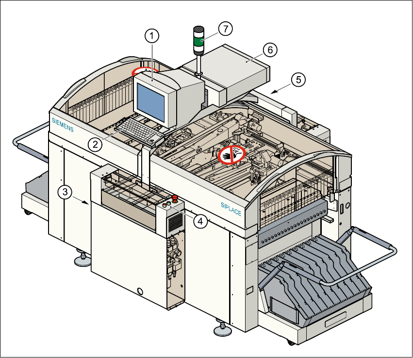
3.1 Machine Displays and Controls
3.1.1 Overview
3
Fig. 3.1 - 1 Overview
Key to Fig. 3.1 - 1
(1) Monitor
(2) Keyboard
(3) Main power switch
(4) Front control panel
(5) Rear control panel
(6) Computer
(7) Main fault indicator