00191297-02.pdf - 第46页
1 Introduction User Manual S-23 HM 1.14 Overview of the modules - vision systems Software Version SR.405.xx 05/99 Issue 44 1.14. 2 T echni cal dat a - PCB vis ion system Fiduci als Up to 3 per placeme nt progr am Local f…

User Manual S-23 HM 1 Introduction
Software Version SR.405.xx 05/99 Issue 1.14 Overview of the modules - vision systems
43
1.14 Overview of the modules - vision systems
Each placement system has 1
– two component vision cameras on the placement heads and
– two PCB vision cameras on the underside of the x axis gantries.
1
The vision analysis unit is located in the control unit for the placement system and the component
vision system is used to determine: 1
– the precise position of the components at the nozzle and
– the geometry of the package form.
1
The PCB vision system uses fiducials on the PCBs to determine: 1
– the position of the PCB,
– its rotation angle
– and the PCB delay.
1
The PCB vision system also uses fiducials on the feeder modules to determine the exact pick-up
position of components, which is particularly important for small components. 1
1.14.1 Technical data - component vision module on the 12-segment revolver head
Maximum component dimensions 18.7 mm x 18.7 mm
Range of components 0402 to PLCC44
including BGA, µBGA, flip-chip, TSOP, QFP
PLCC, SO to SO32, DRAM
Lead spacing > = 0.5 mm
Field of vision 24 mm x 24 mm
Illumination method Front-lighting (3 levels programmable as required)

1 Introduction User Manual S-23 HM
1.14 Overview of the modules - vision systems Software Version SR.405.xx 05/99 Issue
44
1.14.2 Technical data - PCB vision system
Fiducials Up to 3 per placement program
Local fiducials Up to 2 per component (may be of different types)
Library size Up to 255 fiducial types - system fiducials
≥
249
Image processing Gray scale-based correlation
Illumination method Front-lighting
Recognition time per fiducial/ink spot 0.4 s
Field of vision 5.7 mm x 5.7 mm
User Manual S-23 HM 2 Operational Safety
Software Version SR.405.xx 05/99 Issue 2.1 Safety instructions
47
2 Operational Safety
2.1 Safety instructions
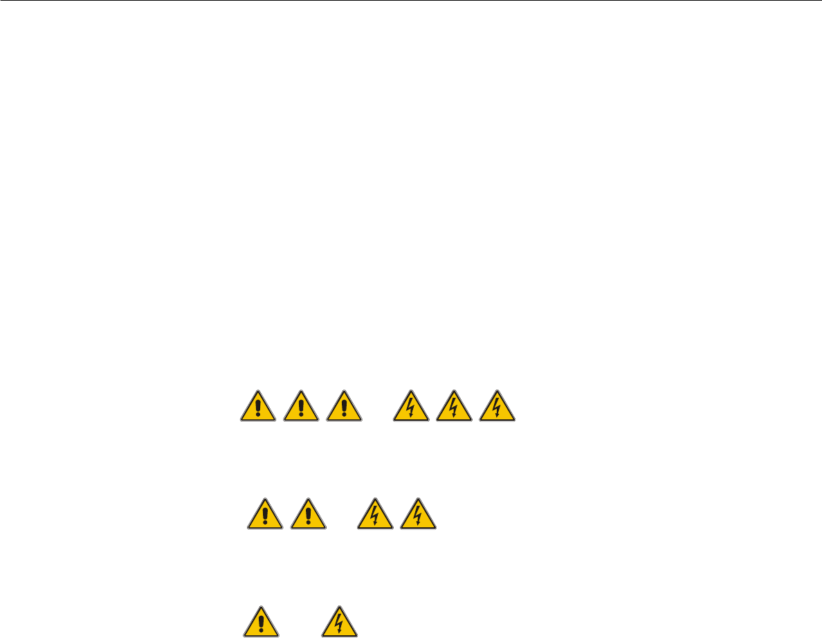
2.1.1 Conventions for the use of hazard symbols
This User Manual contains notes that must be observed to guarantee your personal safety and to
avoid damage to equipment. These notes are highlighted by warning triangles and are indicated
as follows according to the level of risk: 2
2
DANGER or 2
as used in this User Manual means that death, severe injury or considerable damage to equip-
ment may occur if the danger instructions are not followed. 2
2
WARNING or 2
as used in this User Manual means that death, severe injury or considerable damage to equip-
ment may occur if the warning instructions are not followed. 2
2
CAUTION or 2
as used in this User Manual means that slight injury or damage to equipment may occur if the cau-
tion instructions are not followed. 2
2
PLEASE NOTE 2
as used in this User Manual provides information on the product or indicates a part of the User
Manual that requires particular attention. 2
2.1.2 Qualified personnel
Qualified or adequately trained personnel means that these people are familiar with the setting up,
operation and maintenance of automatic placement systems and add-on devices and are suitably
qualified, e.g. 2
– have been trained, instructed or authorized to switch on and off, isolate, earth and identify elec-
trical circuits and system components in accordance with normal safety standards.