00191297-02.pdf - 第35页
User Manual S-23 HM 1 Introduction Software Version SR.405.xx 05/99 I ssue 1.11 Overview of the modules - controls 33 1.1 1 Overview of the modules - controls 1.1 1.1 Controls 1 Fig. 1.1 1 - 1 Overview of the modules - c…

1 Introduction User Manual S-23 HM
1.10 Setting up the placement system Software Version SR.405.xx 05/99 Issue
32
1.10.6 Setting up the placement system
È Raise the placement system using the fork-lift truck and adjust the feet until there is a gap of
830 mm between the top edge of the PCB conveyors and the bottom edge of the feet.
È Leave a gap of 1 to 3 mm between the PCB conveyors of the placement system.
È Use a cord pulled tight to ensure that all the placement systems are exactly in line with one
another.
È Adjust each placement system using a spirit level with an accuracy of 0.02 mm/m.
È Lock the feet in position.
È Check the placement system again using the spirit level and correct the settings, if necessary.
CAUTION
Make sure that you remove all the shipping braces from the placement system. 1
È Fit any components that were dismantled for dispatch.
È Connect all the electrical and pneumatic lines.
RISK OF DEATH
The electrical connection work MUST be carried out only by appropriately trained and certi-
fied personnel. 1
User Manual S-23 HM 1 Introduction
Software Version SR.405.xx 05/99 Issue 1.11 Overview of the modules - controls
33
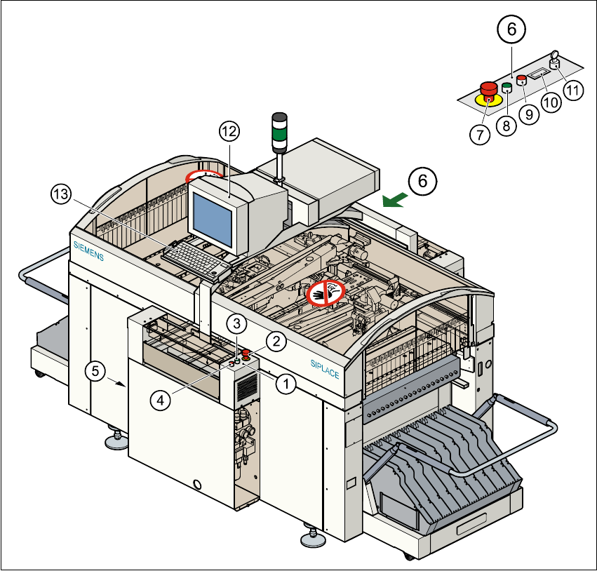
1.11 Overview of the modules - controls
1.11.1 Controls
1
Fig. 1.11 - 1 Overview of the modules - controls
(1) Operator panel, input conveyor (2) Emerg. stop mushroom-head push-button
(3) Start button (white) (4) Stop button (black)
(5) Main power switch (6) Operator panel, output conveyor
(7) Emerg. stop mushroom-head push-button (8) Start button (white)
(9) Stop button (black) (10) Component counter
(11) Key-operated switch (12) Touchscreen monitor
(13) Keyboard with trackball 1

1 Introduction User Manual S-23 HM
1.11 Overview of the modules - controls Software Version SR.405.xx 05/99 Issue
34
1.11.2 Description
All the controls can be reached by a 1.60 m tall person. 1
Main switch 1
The main switch is used to switch the power supply to the placement system on and off. 1
RISK OF DEATH
Some parts inside the placement system carry potentially lethal voltages - even when switched off
at the main switch. 1
Key switch 1
In normal mode, the key switch is set to "0". The key should be removed and kept in a safe place.
It must only be turned to position "I" (set-up mode) by authorized personnel, and then only for cer-
tain maintenance and servicing work. 1
Stop button 1
This button is used to stop the placement system. 1
Start button 1
This button starts the placement system after it has been switched on or after faults have been
eliminated. 1
Emergency stop mushroom-head push-button 1
The emergency stop mushroom-head push-button latches in the ON position when pressed. The
power supply to the gantry axes, the components change-over tables, conveyors, and used tape
cutters is interrupted and the voltage supplied to the star axes of the placement heads is reduced.
Turn the button to release it. 1
Component counter 1
The component counter displays the number of components processed. 1
Station computer, monitor and keyboard 1
The station computer, monitor and keyboard are mounted on a pivoting console on the placement
system’s central cross-beam. The station computer is a desktop model with a Pentium processor.
The operating system is WINDOWS NT 4.0. The SIPLACE graphical user interface, which is
based on the Windows standard, is used to operate and monitor the placement system. A color