00191297-02.pdf - 第26页
1 Introduction User Manual S-23 HM 1.6 The line concept Software Version SR.405.xx 05/99 Issue 24 1.6 The line concept 1.6.1 Overvie w The plac ement sy stem can be linked t o input and out put station s, scr een prin ti…

User Manual S-23 HM 1 Introduction
Software Version SR.405.xx 05/99 Issue 1.5 Description of the machine
23
1.5.3 Technical data - machine overview
Range of components From 0402 to PLCC44, SO32, DRAM, µBGA
Maximum placement speed of the12-nozzle
revolver head (DLM1) 23,000 components/hour
Cycle time at the revolver head 125 ms, regardless of the type of component
Accuracy ± 90 µm at 4 sigma
± 67,5 µm at 3 sigma
PCB format 50 mm x 50 mm to 460 mm x 460 mm
2" x 2" to 18" x 18"
Option: up to 508 mm x 460 mm
up to 20" x 18 "
Feeding capacity Up to 80 tracks, each with 8 mm tapes
Feeder modules Tapes, bulk-cases
Operating system Microsoft Windows NT / RMOS
Combination options Inline or stand-alone
Space required 4 m² / module

1 Introduction User Manual S-23 HM
1.6 The line concept Software Version SR.405.xx 05/99 Issue
24
1.6 The line concept
1.6.1 Overview
The placement system can be linked to input and output stations, screen printing systems, sol-
dering ovens and other automatic placement systems from the SIPLACE range (HS-50, S-20,
F4, F5, and the SIPLACE G glue application station). All SIPLACE modules are supplied with the
necessary data by the UNIX line computer. The placement system can also be linked to a higher
level data processing system through the use of suitable interfaces.
1.6.2 Technical data - line concept
1
System SIPLACE placement lines
Module SIPLACE HS-50 / SIPLACE 80 S-20/ SIPLACE S-23 HM
SIPLACE 80 F4 / SIPLACE F5
Peripherals Input/output stations
Screen printers
Soldering ovens
Inspection stations, etc.
Range of components From 0402 * to 55 mm x 55 mm **
PCB conveyor Automatic width adjustment
PCB format 50 mm x 50 mm to 460 mm x 460 mm
Placement speed
Depends on how the modules are connected to one
another
Space required 4 m² / SIPLACE 80 modules
7.5 m² / SIPLACE HS-50 modules
*
SIPLACE HS-50, SIPLACE 80 S-20, SIPLACE S-23 HM, or SIPLACE 80 F4 with 12-nozzle
revolver head
** SIPLACE 80 F4 / F5
User Manual S-23 HM 1 Introduction
Software Version SR.405.xx 05/99 Issue 1.7 Connection data for the placement system
25
1.7 Connection data for the placement system
1.7.1 Electrical and pneumatic connection points on the placement system
1
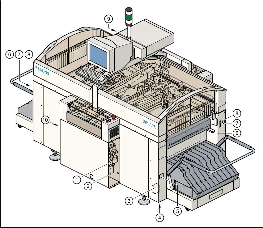
Fig. 1.7 - 1 Electrical and pneumatic connection points on the placement system
(1) Compressed air unit
(2) Connection for compressed air line
(3) Main power filter Z1
(4) Hole for power cable
(5) Service socket
(6) Compressed air supply connection for component changeover table
(7) Power supply connection for component changeover table
(8) Communications connection for component changeover table
(9) LAN connection in the control unit
(10) Main power switch