00191297-02.pdf - 第86页
1 Introduction User Manual S-23 HM 1.15 Overview of the modules - PCB conveyor Software Version SR.405.xx 05/99 Issue 46 The conv eyor be lts are driven by DC moto rs. The liftin g table near th e cente r conve yor clamp…
User Manual S-23 HM 1 Introduction
Software Version SR.405.xx 05/99 Issue 1.15 Overview of the modules - PCB conveyor
45
1.15 Overview of the modules - PCB conveyor
1.15.1 Structure of the PCB conveyor
The placement system is supplied with a single conveyor as standard. A dual conveyor is avail-
able as an option. 1
The left or the right side of the PCB conveyor can be used as the stationary side, as required. 1
1
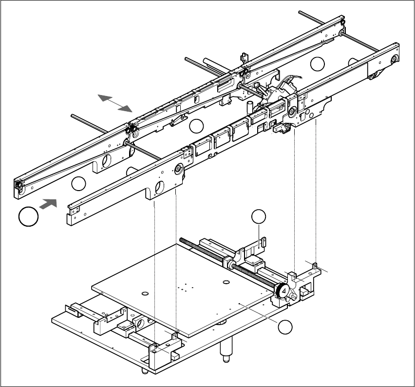
Fig. 1.15 - 1 PCB transport - single conveyor
(1) Input conveyor (2) Center conveyor
(3) Output conveyor (4) Lifting table
(5) Width adjustment T Direction of PCB transport 1
T
4
1
2
3
5

1 Introduction User Manual S-23 HM
1.15 Overview of the modules - PCB conveyor Software Version SR.405.xx 05/99 Issue
46
The conveyor belts are driven by DC motors. The lifting table near the center conveyor clamps the
PCBs in position. The width of the PCB conveyor can be adjusted either 1
– via the menu or
– using the line computer.
1
1.15.2 Technical data - single conveyor
1.15.3 Technical data - dual conveyor
1
PCB format 50 mm x 50 mm to 460 mm x 460 mm
2" x 2" to 18 " x 18 "
Option: upto 508mm x 460mm
upto 20" x 18 "
PCB thickness 0.5 mm to 4.5 mm
Maximum PCB curvature On top: 4.5 mm - PCB thickness
On bottom: 0.5 mm + PCB thickness
Clearance underneath PCB 40 mm
PCB conveyor height 830 ± 15 mm (standard)
Type of interface Siemens (standard)
Clear guide edge of component 3 mm
PCB changeover time 2.5 s
PCB format 50 mm x 50 mm to 460 mm x 216 mm
2" x 2" to 18" x 8.5"
Option: upto 508mm x 216mm
upto 20" x 8,5"
Fixed edge of conveyor Right (standard), left (option)
Placement sequence per conveyor Synchronous: same or different
Asynchronous: same
PCB width per conveyor Synchronous: different
Asynchronous: same
Ink spot recognition Synchronous: not possible
Asynchronous: possible
Automatic width adjustment Synchronous: not possible
Asynchronous: possible

User Manual SIPLACE S-23 HM 3 Introduction and Basic Concepts
Software Version SR.405.xx 05/99 Issue
85
3 Introduction and Basic Concepts
This chapter describes the machine displays and controls together with the components of the
graphic user interface.
3
It also provides a basic understanding of the use of the user interface and its functions. 3
NOTE
It is essential for operators who are not yet familiar with the user interface of the station computer
software (SC software) to read this chapter. 3