00191297-02.pdf - 第89页
User Manual SIPLACE S-23 HM 3 Introduction and Basic Concepts Software Vers ion SR.405.xx 05/99 Iss ue 3.1 Machine Displays a nd Controls 87 3.1.1.1 General Every statio n is equi pped wi th a station c omputer . The sta…
3 Introduction and Basic Concepts User Manual SIPLACE S-23 HM
3.1 Machine Displays and Controls Software Version SR.405.xx 05/99 Issue
86
3.1 Machine Displays and Controls
3.1.1 Overview
3
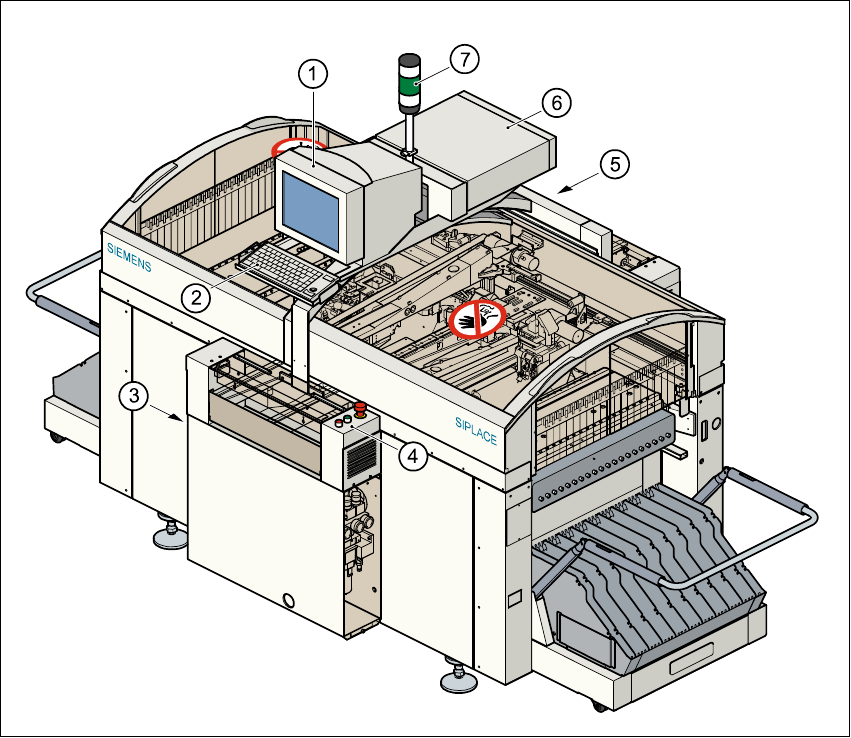
Fig. 3.1 - 1 Overview
Key to Fig. 3.1 - 1
(1) Monitor
(2) Keyboard
(3) Main power switch
(4) Front control panel
(5) Rear control panel
(6) Computer
(7) Main fault indicator

User Manual SIPLACE S-23 HM 3 Introduction and Basic Concepts
Software Version SR.405.xx 05/99 Issue 3.1 Machine Displays and Controls
87
3.1.1.1 General
Every station is equipped with a station computer. The station computer, monitor and keyboard
are mounted on a pivoting console above the placement system.
There is an operating panel on both the input and the output side of the placement system. Each
panel has a Start and a Stop button, an emergency stop mushroom-head push-button, a key
switch and a component counter.
NOTE
You can operate the SR software interface either via the keyboard and trackball or via the touch
screen (see section 3.2.1). 3
The position of the switches and buttons (main switch, key-operated switches, start/stop button,
EMERGENCY STOP button etc.) is illustrated in Figure 3.1 - 2. The functions are described in
Chapter 2.
3
WARNING
The machine base doors may only be opened by qualified personnel since certain machine
components carry hazardous voltages.
The relevant accident prevention and applicable regulations (DIN) regarding electrical/electrome-
chanical installations must be strictly complied with. Failure to do so may result in death, severe
physical injury or considerable damage to property. 3
3
3
3
3 Introduction and Basic Concepts User Manual SIPLACE S-23 HM
3.1 Machine Displays and Controls Software Version SR.405.xx 05/99 Issue
88
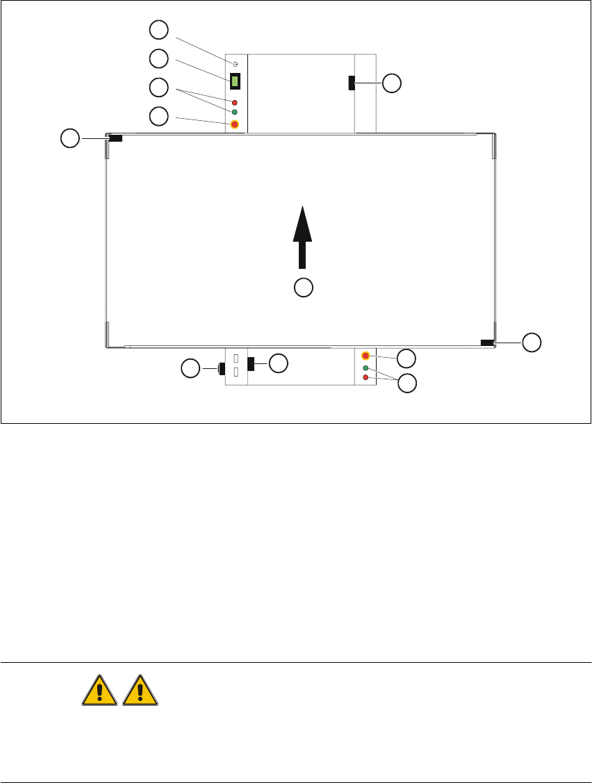
3.1.2 Machine Switches and Buttons
The figure below presents the position of the switches and buttons on the machine. 3
3
Fig. 3.1 - 2 Position of switches and buttons on the machine
Key to Fig. 3.1 - 2
WARNING
Only appropriately qualified personnel are permitted to use the key-operated switch for service or
maintenance work. The key musµµt be removed to prevent unauthorized access as otherwise
serious injury to personnel or damage to the machine may occur. 3
(1) Key-operated switch (2) Component counter
(3) Start and stop buttons (4) Emergency stop mushroom-head push-button
(5) Cover switch, lefthand side (6) Main switch
(7) Cover switch, cover of input conveyor (8) Cover switch, righthand side
(9) Cover switch, cover of output conveyor (10) Direction of PCB transport
1
2
3
4
5
6
7
10
4
3
8
9