00191297-02.pdf - 第78页
2 Operational Safety User Manual S-23 HM 2.6 Lock out and tag out procedure Software Version SR.405.xx 05/99 Issue 78 2.6 Lock out and t ag out procedure 2.6.1 Purpose and scope Before pe rforming a ny mai ntenance work …
User Manual S-23 HM 2 Operational Safety
Software Version SR.405.xx 05/99 Issue 2.5 Energy state of the machine after switching off at the main switch
77
2.5.1 Placement system switched off at the main switch, but still connected ...
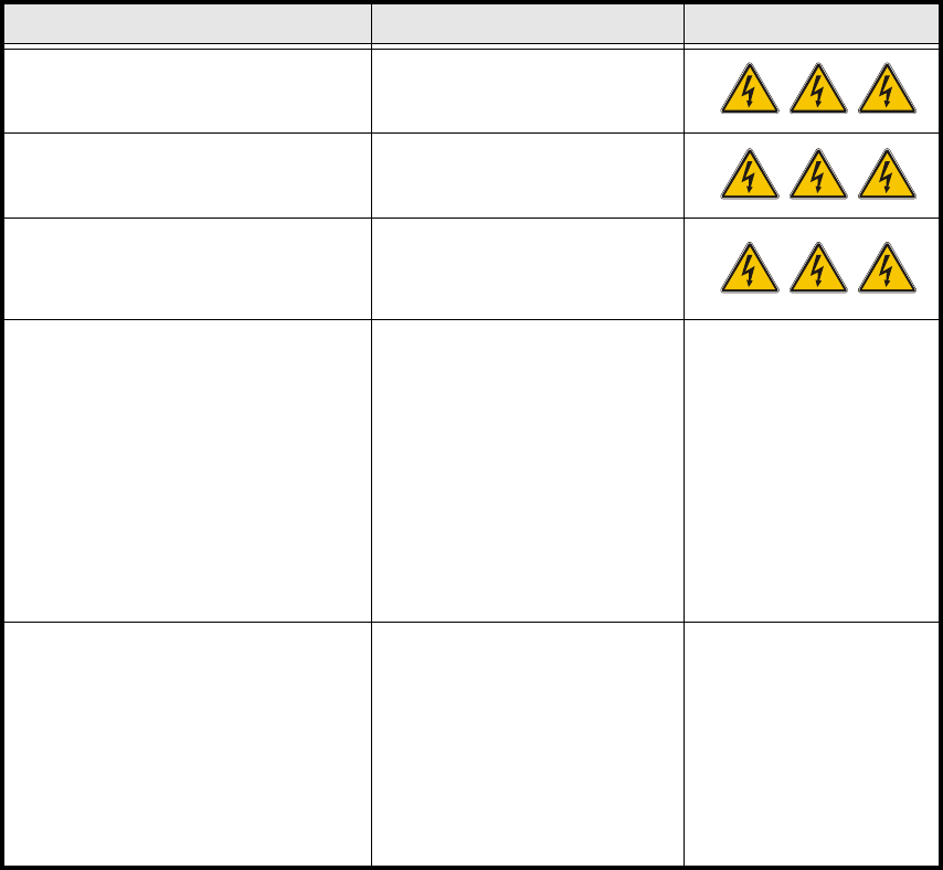
The following table specifies the voltages of assemblies when the automatic placement system is
switched off at the main switch, but still connected to the mains supply. 2
2.5.2 Placement system switched off at the main switch and disconnected ...
The automatic placement system is unpowered, apart from slight residual voltages in the servo
unit. 2
2.5.3 Compressed air conditions in the machine after switching off at the main
switch
When the system is switched off at the main switch (item 1 in Fig. 2.5 - 1) or if the power supply
fails, the electrically-controlled main valve Y1 of the compressed air unit closes (Fig. 2.4 - 1,
page 75 ). The pressure will drop to 0 bar within 5 seconds. 2
Assembly Voltage
Main power filter Z1
Terminals L1, L2, L3
3 x 400 VAC (3 x 208 VAC)
Service socket
230 VAC(115 VAC)
Main switch Q1
Terminals 1, 3, 5
Terminals 2, 4, 6
3 x 400 VAC (3 x 208 VAC)
0 VAC
Servo unit (Item 7 in Fig. 2.5 - 1)
Test socket 001
Test socket 002
Test socket 003
Test socket 004
Test socket 005
Test socket 006
Test socket 008
Test socket 009
GND 007
< 12 VDC
< 12 VDC
< 12 VDC
0 VDC
0 VDC
0 VDC
< 12 VDC
< 12 VDC
Control unit (Item 6 in Fig. 2.5 - 1)
Test socket 5 V
Test socket + 12 V
Test socket – 12 V
Test socket + 15 V
Test socket – 15 V
Test socket + 24 V
GND
0 VDC
0 VDC
0 VDC
0 VDC
0 VDC
0 VDC
Tab. 2.5 - 1 Voltages of assemblies when the automatic placement system is switched off at the main switch,
but still connected to the main power

2 Operational Safety User Manual S-23 HM
2.6 Lock out and tag out procedure Software Version SR.405.xx 05/99 Issue
78
2.6 Lock out and tag out procedure
2.6.1 Purpose and scope
Before performing any maintenance work or service work, a procedure of locking and tagging
must be followed. The procedure, when followed correctly eliminates the possibility of an em-
ployee being injured. 2
NOTE 2
These procedures represent the minimum lock/tag out requirements. Any additional safe-guards
needed to complete work safely can be specified by facilities supervision, the safety officer, the
safety committee and the health department.
2.6.2 Description
Whenever it becomes necessary to isolate, control and release energy, the following procedure is
to be followed 2
1. Notify affected employees.
2. Shut down equipment, using normal stopping procedures, such as
– depressing the stop button
– shutting down the station computer or
– switching off the placement system at the main switch.
3. Isolate the equipment from all its energy sources such as
– compressed air supply and
– power supply.
4. Lock Out equipment
– Apply the lock and the lockout whenever possible.
– The Tag Out alternative:
If a machine can be locked out, it must be. However, there are situations where energy iso-
lating devices can not accommodate locks. In these cases, the energy isolating devices
must be tagged to warn employees that the machine is de-energized for servicing. The tag
must be securely fastened, it must be placed in a position visible to all and it may only be
removed by the person who attached it. 2
5. Relieve stored energy
User Manual S-23 HM 2 Operational Safety
Software Version SR.405.xx 05/99 Issue 2.6 Lock out and tag out procedure
79
Stored energy in the compressed air supply or electrical energy in electrolytic capacitors must
be released by appropriate means. 2
– After switching off the placement machine wait until the voltages and the compressed air
have discharged to be able work without any risk.
6. Verify the lock out.
– Testing the lock out can be done simply by pressing the start button.
7. The following steps must be taken to restore the machine to operation.
8. Check the area, authorized employees should remove all of their tools and reinstall all guards.
9. Notify all affected employees.
Before removing even one lock or tag, inform all workers in the area that the machine is going
to be restarted. 2
10.Remove locks/tags
Each authorized employee must remove his or her own lock. Each authorized employee will
have his or her own lock. 2
11.Turn the machine on. Authorized workers should observe the equipment in operation to insure
repairs were done correctly.
2.6.3 Testing
The maintenance or electrical person may test the circuits by energizing the circuit for a short
period of time without voiding the lock out procedure provided. This may be done only when no
other work is being performed by any other person on the equipment being tested. 2
It is extremely important that all remote start switches be tagged with the “Do Not Operate” tag to
prevent inadvertent operation of the equipment during these periods. 2