FX-3RA_SPE_EN.pdf
High - Spee d Modular M ounter FX - 3R A PRODU CT SPE CIFICA TIONS
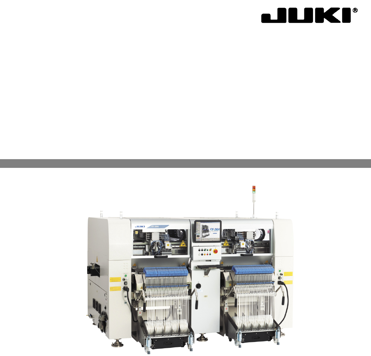
High-Speed Modular Mounter
FX-3RA
PRODUCT SPECIFICATIONS

Important
(1) No part of this document may be copied or reproduced without the prior
permission of JUKI Corporation. (Including software and program)
(2) The contents of this document are subject to change without notice.
(3) This manual is prepared with extreme care. However, if you have any question
or find any error or omission in writing, contact our dealer or JUKI Corporation.
(4) JUKI Corporation shall disclaim all the responsibility for any trouble resulting
from the user's abnormal operation regardless of Item (3).
(5) Microsoft, Windows are registered trademarks or trademarks of Microsoft
Corporation in the United States and /or other countries.
The company names and product names mentioned in this document are
generally registered trademarks or trademarks of the respective companies.
Table of contents
1. GENERAL ...................................................................................................................................1
2. FEATURES .................................................................................................................................2
3. SYSTEM CONFIGURATION ......................................................................................................5
4. SPECIFICATIONS.......................................................................................................................7
4-1. Basic specifications ...........................................................................................................7
4-2. Mechanical/Electrical Specifications .................................................................................8
4-2-1 Usage environment conditions ......................................................................................8
4-2-2 Outside dimension (except for the largest projections) ................................................9
4-2-3 Mass ................................................................................................................................9
4-3. Component placement Cycle Time
(A number of components to be placed per an hour).....................................................9
4-4. Nozzles ............................................................................................................................10
4-5. Applicable Component ....................................................................................................11
4-5-1 Applicable component sizes ....................................................................................... 11
4-6. Component Placement Accuracy at X, Y and θ ..............................................................11
4-7. Applicable PWBs .............................................................................................................12
4-7-1 PWB flow direction ...................................................................................................... 12
4-7-2 PWB sizes and Mass .................................................................................................. 12
4-7-3 A range not available to place a component .............................................................. 12
4-7-4 A range not available to set up the support pins ........................................................ 13
4-7-5 Ranges available to place the components on the PWB front and back surfaces ... 13
4-7-6 Function correcting the PWB positions ...................................................................... 15
5. STANDARD FUNCTIONS AND OPTIONAL FUNCTIONS ......................................................18
5-1. Standard Functions .........................................................................................................18
5-1-1 Height Measurement System (HMS) ..........................................................................
18
5-1-2
Vacuum pump ............................................................................................................. 18
5-1-3 Feeder Float Detecting Sensor ................................................................................... 18
5-2. Option ..............................................................................................................................18
5-2-1 Bad Mark Reader (BMR, Factory-Set Option) ........................................................... 18
5-2-2 Feeder Trolley Exchange Function (Factory-Set Option) .......................................... 19
5-2-3 Rear Side Operation Unit (Factory-Set Option) ......................................................... 19
5-2-4 Components verification System (CVS, Factory-Set Option) .................................... 19
5-2-5 Feeder Indicator Function (FPI, Factory-Set Option) ................................................. 20
5-2-6 SOT Direction Check Function (Factory-Set Option) ................................................ 20
5-2-7 Longer sized PWB in X axis (Factory-set option) ...................................................... 20
5-2-8 Solder Recognition Lighting (Factory-set option) ....................................................... 21
5-2-9 Component Quantity Control (Option) ........................................................................ 21
5-2-10 Connector Bracket (Factory-set option Designed for the Fixed Bank) ................... 21
5-2-11 Handheld Operating Device (HOD: Factory-set option) .......................................... 21
5-2-12 Placement Monitor (Factory-Set Option) .................................................................. 22
5-2-13 IC Collection Belt (Option) ......................................................................................... 25
5-2-14 Flexible Calibration System, The adjustment jig (FCS:Option) ............................... 25
5-2-15 Software to support production(Option) ................................................................... 26