FX-3RA_SPE_EN.pdf - 第28页
- 24 - Computer specifications for placement monitor Spe cification r ecommended for a Placeme nt Monitor CPU 2.66 GHz or higher ( Intel Core ™ Quad or higher) Memory 4 GB or more HDD capacity C dri ve : 750 GB or more (…
- 23 -
(8) Board barcode recognizing function (for a barcode/2-D code)
When you use the function for recognizing a barcode or a 2-D code on a board (optional),
you can set the board code in the database of shot images.
Barcode reader assembly
Barcode: The system reads a 1-D barcode on the topside of a board from the upper
section of the board loading entrance.
2-D code: The system reads a 2-D code on the topside of a board with the OCC
attached on the head.
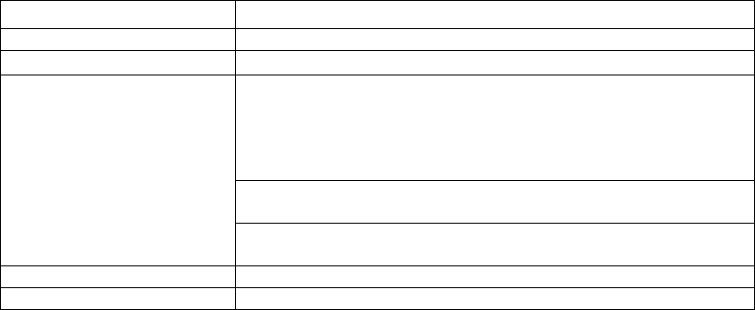
Specifications of the Placement monitor
View field
10.3×6.1mm
Focus height
Board top surface height (0.0 mm)
Focus depth
±
2 mm
Captured images
approximately 200 KB (**.bmp)
approximately 50 to 120 KB (**.png)
(For a single placement component, two photos of pre-pickup
and post-pickup and 2 photos of pre-
placement and
post-placement are taken.) Default value (Note 1)
Approx. 52.8 GB for one hour (Note 2)
(Approx. 200 KB x 4 images x 66,000 CPH) (Pattern IPC9850)
Approx. 6.9 TB for one week (Approx. 52.8 GB x 22 hours x 6
days)
Supported languages
English and Japanese
Destination
Europe, Japan, China and Southeast Asia
* When the placement monitor is used, the placement cycle time of 3% max. becomes slower.
When the “
The system pauses if a component existence error occurs” is used in the placement
monitor setting, the placement cycle time of 40% max. becomes slower.
* When a nozzle No. 505/506 is used, the operation for placing components has been changed
so that the nozzle might not glitter when a photo is taken. As a result, the placement operation
for using nozzle No. 505/506 becomes 18 ms slower per one placement point than that for not
using a placement monitor.
* When the applicable language of the machine proper is Chinese, an application of the
placement monitor is expressed in English.
Note 1: The mode of taking five photos (at placement of components) can be set. When this
mode is actually set up, the placement cycle time becomes a maximum of 35%
slower.
Note2: This capacity is a total of left and right stations (2 computers) in the case where 4
photos are taken for a single placement component.
- 24 -
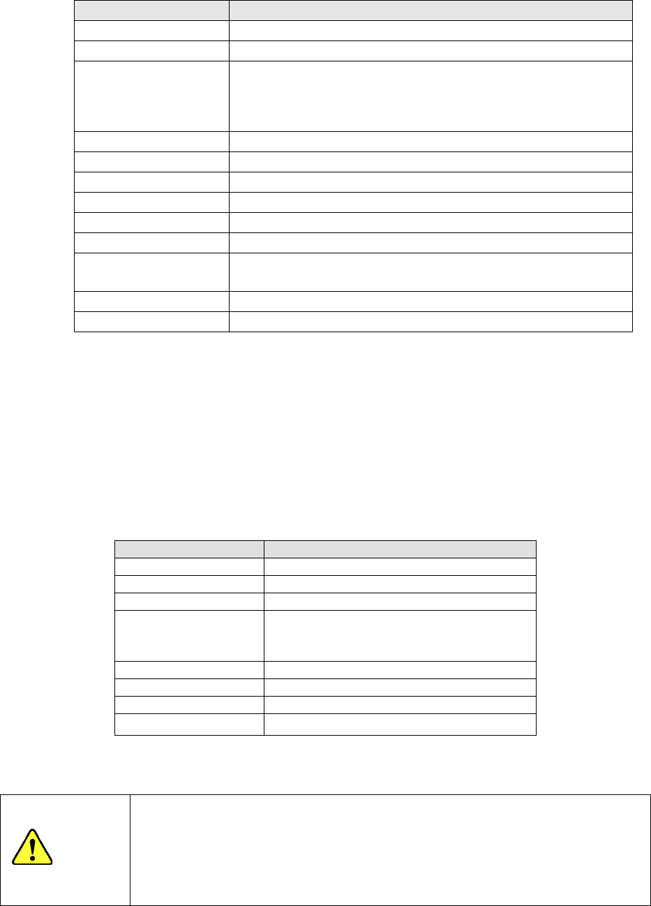
Computer specifications for placement monitor
Specification recommended for a Placement Monitor
CPU
2.66 GHz or higher (Intel Core™ Quad or higher)
Memory
4 GB or more
HDD capacity C drive:750 GB or more (SATA)
D drive:2.25 TB or more (SATA ,RAID 0)
(Create C drive and D drive; create the data storage area in D drive.)
See Notes 1 and 2.
Chipset
Intel X58 chipset or, or the equivalent
DVD-ROM Drive
One
USB port
1 port or more
LAN port
1 port or more
Monitor resolution
1024 × 768 or higher
Expansion slot
PCI bus, full-sized 1 slot*
OS Microsoft Windows 7 Professional 32bit
(The OS has to be clean-installed,)
Software
Any software other than designated one must not be installed.
Recovery medium
OS recovery kit
Note1 Do not configure the D: drive with any external hard disk drive.
Note2 The HDD capacity of the recommended specifications is approximately 1.3 M images
(**.bmp) (equivalent to 2.6 M components).
Note3 You have to add an IEEE1394a expansion card designated by JUKI to communicate
with a mounter.
Reference model: DELL Precision T3500 Mini Tower Mode Package or the equivalent is used as
the reference model.
If the reference model cannot be purchased, select a reference model by referring to computer
specifications.
Reference model
Model
Dell Precision T3500 Mini Tower Mode
CPU
Intel Xeon™ W3530
(
2.80 GHz
)
Memory
4 GB
HDD capacity C drive:1TB (SATA)
D drive:1.5TB×2 (SATA ,RAID 0)
(
※
RAID will be set up after purchase)
Chipset
Intel X58 chipset
DVD-ROM Drive
One
OS
Microsoft Windows 7 Professional 32bit
Recovery medium
OS recovery kit
* Intel, Core and Xeon are trademarks of Intel Corporation in the U.S.A. and other countries.
* Dell and Dell Precision are trademarks of Dell Inc. in the U.S.A. and other countries.
Precautions for preparing a computer for the Placement Monitor system
Do not install any software other than the applications of Placement Monitor
to avoid communication failures. If other software (such as a writing
software, DVD player, printer support software or others that run in the
background) exists, a clean install of the OS is required.
CAUTION
- 25 -
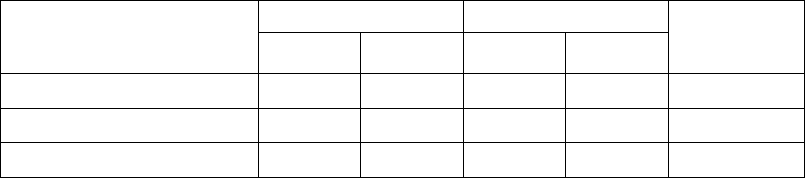
Combination that permits installing the placement monitor and number of computers
required
One computer is required for one station.
Combination that permits
installing the placement
monitor
Left station Right station
Number of
computers
required
LF head LR head RF head RR head
All heads
○ ○ ○ ○
2
Left station only
○ ○ ― ―
1
Right station only
― ― ○ ○
1
○: Head for installing the placement monitor
5-2-13 IC Collection Belt (Option)
This belt collects IC components whose lead is found to be bent or float with the VCS by
separating them one by one.
The feed pitch setting can be changed just by your entering a new value.
- Applicable component size: 10 x 10 mm to 50 x 50 mm,
Height: 1 mm or higher
- Belt feeding pitch: 15 mm to 55 mm (in increments of 5 mm)
- Number of components
which can be collected: 5 to 16
- Number of occupied positions: 9
5-2-14 Flexible Calibration System, The adjustment jig (FCS:Option)
After a jig component that is recognized with laser is placed on a glass jig board, the Flexible
Calibration System (FCS) uses a camera to automatically measure the difference between a
value set with the program and the position at which the component is placed, and
calculates the offset value to be used for placing the component.
This series of operations are automatically performed with your setting of a board and
loading of a program into the system.
When you use the FCS, you can check whether the precision is maintained and adjust the
precision at relocation or routine maintenance.