FX-3RA_SPE_EN.pdf - 第42页
- 38 - S tick feeder for mechanical bank ・ Feeder type: T ype N (SFN*AS) Mode l Lane wi dth [m m] SOP SOJ PLCC(QFJ ) Nominal size [mil] Element wid th [mm] Element height [mm] Nominal size [mil] Element width [mm] Elemen…
- 37 -
6-3-7 Electric Trolley Power Station
Power supply for an electric feeder exchange trolley
This is an optional unit that supplies power to a feeder exchange trolley for an electric feeder
in order to set a tape onto an electric tape feeder (ETF type) without removing the feeder
from the electric feeder exchange trolley. This shall be used for an electric feeder
exchange trolley only.
(1) Specifications
Model
PW01
Power supply
100 – 120 V/200 – 240 V AC
Frequency
50/60Hz
Rated power
600VA
Output voltage
24 V ± 10 % DC
Output current
9.0A(Max)
External dimensions
(L/W/H)
200mm×260mm×545mm
Mass
Approximately 9.0 kg
6-4. Stick feeder (mechanical bank)
A stick feeder is driven by the belt without requiring any power supply or air supply.
It feeds an ordinary SOP, SOJ and PLCC that are packed in a stick.
For components other than those in the following table of the stick package, consult with JUKI
or the agent.
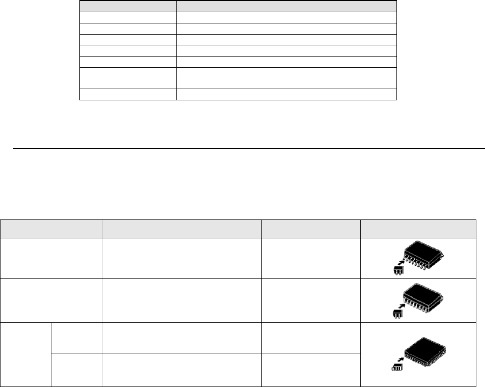
Applicable element Type N Type W Element shape
SOP
(over 8 pin)
225 mil, 300 mil, 375 mil, 450 mil 525 mil, 600 mil
SOJ 300 mil, 350 mil, 400 mil, 450 mil -
QFJ
(PLCC)
Square 350 mil, 450 mil
650 mil, 750 mil,
950 mil, 1,150 mil
Rectangle
285×425 mil, 290×490 mil,
350×550 mil, 450×550 mil
-
- 38 -
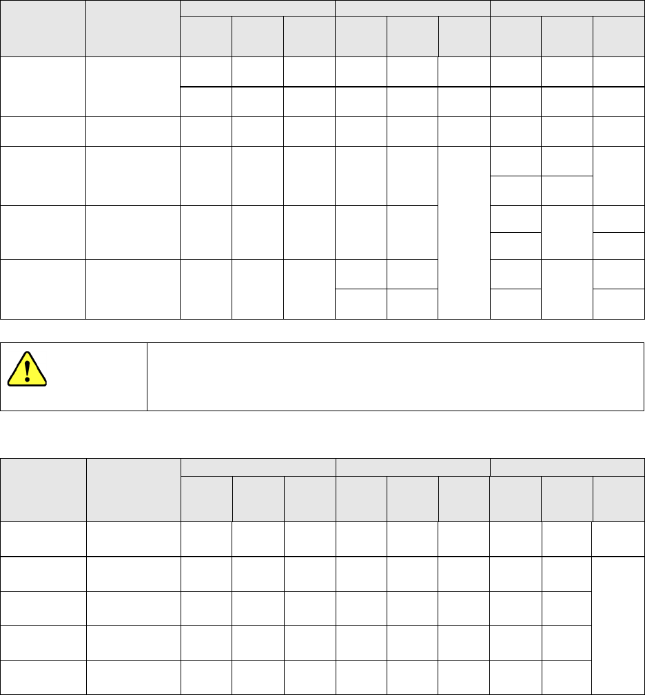
Stick feeder for mechanical bank
・Feeder type: Type N (SFN*AS)
Model Lane width [mm]
SOP
SOJ
PLCC(QFJ)
Nominal
size
[mil]
Element
width
[mm]
Element
height
[mm]
Nominal
size
[mil]
Element
width
[mm]
Element
height
[mm]
Nominal
size
[mil]
Element
width
[mm]
Element
height
[mm]
SFN0AS
(Type N0)
At delivery:
6.9
Adjustment range:
6.6~9.2
225
5.72
~
6.99
~1.5
300
7.62
~
8.89
2.0
SFN1AS
(Type N1)
7.2 225
5.72~
6.99
1.5
SFN2AS
(Type N2)
9.2 300
7.62~
8.89
2.0 300
8.38~
8.76
3.25~
3.76
285×
425
8.05
~
8.31
4.20~
5.08
290×
490
8.13~
8.51
SFN3AS
(Type N3)
11.2 375
9.35~
10.8
2.5 350
9.65~
10.03
350
9.78~
10.03
4.20
~
4.57
350×550
4.20~
5.08
SFN4AS
(Type N4)
13.0 450
11.43~
12.7
3.0
400
10.92
~
11.30
450
12.32~
12.57
4.20~
4.57
450
12.19~
12.57
450×
550
4.20~
5.08
Use a dedicated stick feeder matched to each element size. Otherwise,
elements may be broken due to inaccurate operation even if they are
caused to flow.
・Feeder type: Type W (SFW*AS)
Model
Lane width
[mm]
SOP
SOJ
PLCC(QFJ)
Nominal
size
[mil]
Element
width
[mm]
Element
height
[mm]
Nominal
size
[mil]
Element
width
[mm]
Element
height
[mm]
Nominal
size
[mil]
Element
width
[mm]
Element
height
[mm]
SFW1AS
(Type W1)
15.0 525
13.34~
14.61
3.5
SFW2AS
(Type W2)
18.2 600
15.24~
16.51
4.0 650
17.40~
17.65
4.20~
5.08
SFW3AS
(Type W3)
20.8 750
19.94~
20.19
SFW4AS
(Type W4)
26.0
950
25.02~
25.27
SFW5AS
(Type W5)
31.2
1150
30.1~
30.55
- For Types N1 to N4 and types W1 to W5, an optional spacer kit is available for a change to another type.
- Type N0, the clearance can be finely adjusted by attached spacer to secure the lane width for SOP 8 pins and
10 pins.
CAUTION

- 39 -
7. CONTROL SYSTEM
7-1. Saving a program
FX-3RA mounter stores a production program onto the SSD in the main unit.
When you use a USB port, you can store it on an external storage device also.
7-2. Limit of a production program
● Maximum number of placement points per circuit : 10,000 points
● Maximum number of circuits per PWB : 1,200 for a matrix board
200 for a non-matrix board
● Maximum number of points per PWB : 10,000 points
● Maximum number of component data records : maximum number of component
types that can be attached on the machine
● Maximum number of component pick-up records : same as the above.
● Maximum number of Area Fiducial marks :
50 sets for area marks/component placement positioning mark,
1 set for a BOC mark (2 to 3 marks)
7-3. Production Mode
The following three production modes are available during production:
PWB production
- Specifies the number of PWBs you plan to produce and produces PWBs actually.
Trial mode
- Performs a trial PWB production.
You can select the PWB pick-up position tracking function or PWB placement position
tracking function that is to be performed after placement.
Dry run mode
- Checks the PWB pick-up/placement process without using any component.
You can select the PWB pick-up/placement position tracking function.