FX-3RA_SPE_EN.pdf - 第13页
- 9 - 4-2-2 Outs ide dimension (except for the la rgest projections) L- PW B , L- W ide - P W B s pec ifi cat ion (Unit: mm) 2 0 20/ 2 070 16 50 (L , L - Wid e ) 24 20 (L , L - Wid e ) 26 50 (L ) , 28 80 ( L- Wi de ) 基板搬…
- 8 -
4-2. Mechanical/Electrical Specifications
4-2-1 Usage environment conditions
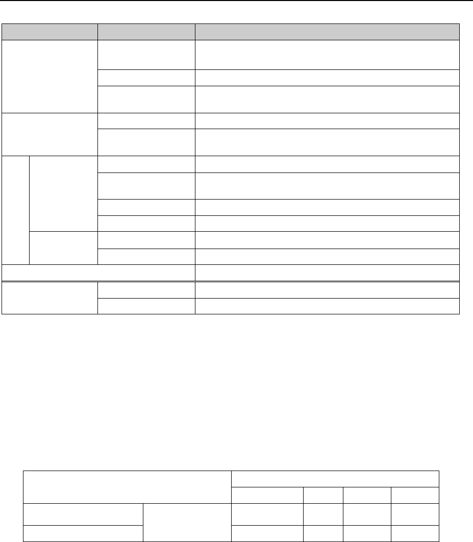
FX-3RA
Power supply
Voltage
Three-phase 200V, 220V, 240V, 380V, 400V, 415V AC ±10%
(see Note 1)
Frequency 50/60 Hz
Rated apparent
power
Maximum 8.5 kVA
Air supply
Air pressure 0.50 ± 0.05 MPa dry air
Maximum air
consumption
150 L/min (ANR) (see Note 2)
Environment
requirements
During
operation
Temperature
10°C to 35°C
Accuracy guaranteed
temperature
20°C to 25°C
Humidity 30 to 80% RH (No condensation)
Altitude 1,000m or less
Transportation
or storage
Temperature
-15°C to 70°C
Humidity 20% to 95%RH (No condensation)
Noise 75 dB (A) or less (see Note 3)
Installation conditions
(For EN machine)
Overvoltage category Category Ⅲ according to IEC60664-1
Pollution degree Degree 3 according to IEC60664-1
Note 1: Any power supply cable for the primary side is not supplied with the machine.
We make no warranties against any accident of the primary side wiring caused by
short-circuit of a power cable and so on. Be sure to select the appropriate breaker
and power cable at your own risk.
Use a 8-mm
2
or more diameter of a power cable for each phase at the primary side.
Note that the appropriate cross-section area of a power cable varies depending on
its class, facility condition, length and the supplied power voltage. Therefore, be
sure to use a power cable that conforms to the regulations of the installation site.
Applicable sectional areas of primary side power cable lengths
Supply power
Primary-side power cable length(m)
Less than 20m 30m 40m 50m
AC 200/220/240V
Applicable
sectional area
(mm
2
)
8 8 10 12
AC 380/400/415V 8 8 8 8
Note that a 3-phase 50 A breaker is attached on the power supply incoming section
of FX-3RA.
Peak current (when 200 V AC 3-phase power supply is used): 90 A
Note 2: About ANR: Temperature 20
°
C,Absolute pressure 0.1 MPa (= 100 kPa=1 bar) and
Relative humidity 65%
The necessary air supply shall be calculated as follows:
In case of 150 L/min (ANR), 150/0.926 = 162 L/min: 162 L/min or more air supply
is required.
Note 3: This value was measured with conforming to the JIS Z8731 regulation.
- 9 -
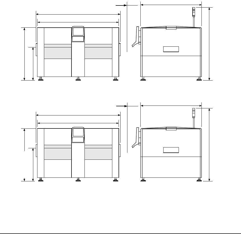
4-2-2 Outside dimension (except for the largest projections)
L-PWB, L-Wide-PWB specification (Unit: mm)
2020/2070
1650 (L,L-Wid e )
2420(L,L-Wid e )
2650(L) , 28 80 ( L-Wi de )
基板搬送高さ
900/950
1530/1580
1995/2045
XL-PWB specification
2020/2070
1850
2430
2880
基板搬送高さ
900/950
1530/1580
1995/2045
4-2-3 Mass
L-PWB、L-Wide-PWB specification: 3,500kg
XL-PWB specification: 3,750kg
4-3. Component placement Cycle Time (A number of components to
be placed per an hour)
L-PWB、L-Wide-PWB specification: 66,000 CPH (IPC9850)
XL-PWB specification: 51,500 CPH (IPC9850)
*1: This is a number of components to be placed for one hour when 400 1608, 1005 or
0603 components are placed onto 200 mm × 200 mm board at an angle of 0, 90, 180
and 270 degrees sequentially.
*2: The mounter places a 0402 component sequentially, and the cycle time is 51,500CPH
(for L, L-wide PWB) and 40,500CPH (for XL PWB).
*3: When you use the 0402 component support function to place a 0402 component on a
board, the mounter does not pick up two or more 0402 components simultaneously.
However, it can pick up a 0402 component(s) and other type component(s)
simultaneously if the other head is located within the simultaneous pick-up area viewed
from the placement head for a 0402 component.
*4: When the placement monitor is used, the placement cycle time of 3% max. becomes
slower. When the “The system pauses if a component existence error occurs” is used
in the placement monitor setting, the placement cycle time of 40% max. becomes
slower.
Conveyor height
Conveyor height
(90)
(90)
- 10 -
4-4. Nozzles
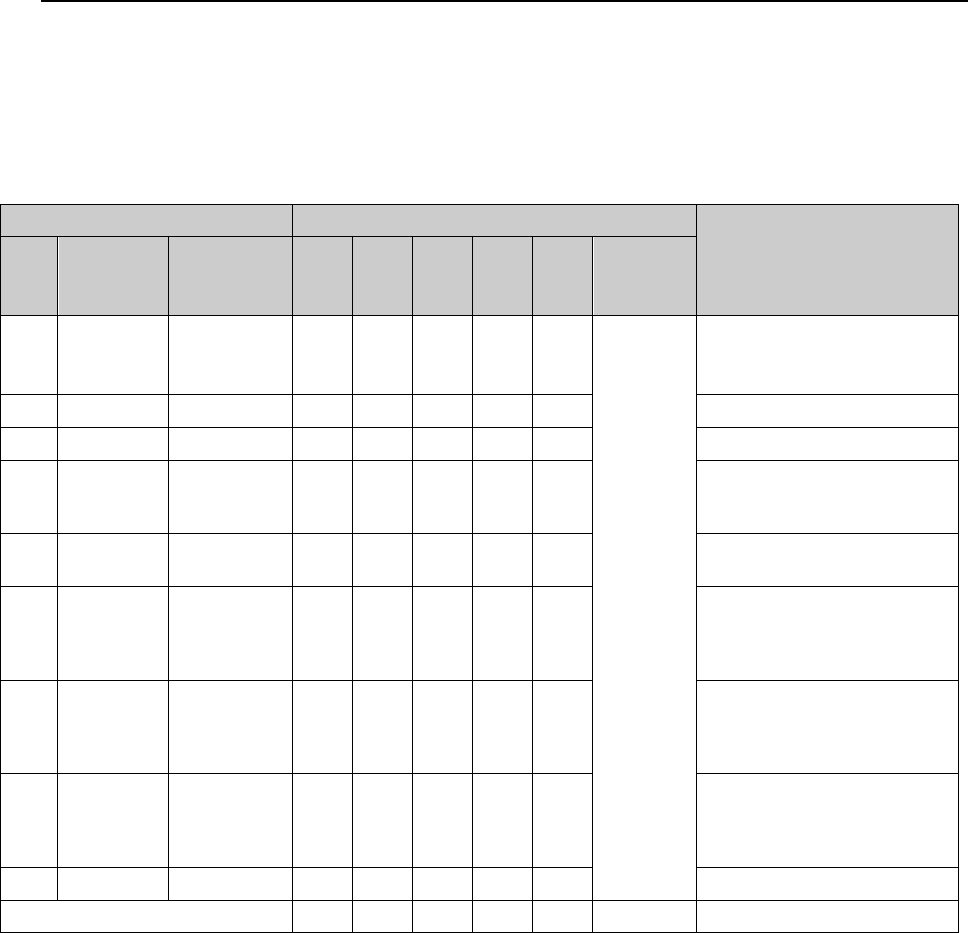
Various types of nozzles have been designed to increase the reliability of placement of each
type of components as shown in the table below. Nozzles whose number is from 500 to 509
are used for both laser recognition of components and vision
You can select one of the nozzle sets shown in Table as the standard nozzles supplied with
FX-3RA products.
Table Nozzles supplied as the standard devices
Nozzle Nozzle assembly
Applicable components
(reference) and remarks
NO.
Internal
diameter
of a nozzle
External
diameter of
a nozzle
A B D E F
Std.
Nozzle
slection
500
2-φ0.4
1.0 x 0.5 - 24 - - 18
Note.1
1005, 1608, 2012
*See
Note 2
SOT (Molding: 1.6 x 0.8)
501
φ0.25
0.7 x 0.4 - - - 18 18 0603
502
φ0.4 φ0.7
24 - 24 24 1005
503
φ0.6 φ1.0
24 - 18 12 -
1608, 2012,
SOT (Molding: 1.6 x 0.8),
SOT (Molding: 2.0 x 1.25)
504
φ1.0 φ1.5
- 12 12 6 6
2012, 3216, SOT23, SOT
(Molding: 2.0 x 1.25)
505
φ1.7 φ3.5
4 4 4 2 2
Aluminum electrolytic
capacitor
(small), tantalum electrolytic
capacitor, trimmer
506
φ3.2 φ5.0
4 - 2 - -
Aluminum electrolytic
capacitor (medium),
SOP (narrow type),
SOJ, Connector
507
φ5.0 φ8.5
4 - - - -
Aluminum electrolytic
capacitor (large),
SOP (wide type),
TSOP, QFP, PLCC, Connector
508
φ8.0 φ9.5
4 4 4 4 4 QFP, PLCC, BGA
Total number of nozzles 64 44 64 66 48 44
* Nozzles other than the supplied ones are optional.
* A nozzle assembly for a CVS is provided with the same number of nozzles.
* Total number of nozzles that can be installed onto an ATC station: 72. (18 nozzles for one
unit × 4 units)
Note1: As a set of standard nozzles (descried in the column “Std. Nozzles selection” above), you
can select 44 nozzles among those whose number is from 500 to 508C.
However, you have to select a nozzle to be used for calibration of the machine:
・ For laser calibration (one of the nozzles:500, 502 and 503)
・ For image calibration (508 nozzle)
Note 2: Since a theta error may occur due to the shape of the surface of a 2012R component to be
picked (such as differences of manufactures and/or resistance values), use a No. 504
nozzle if you have to place 2012R components in the high density (the gap between the
adjacent components: 0.3 mm or less).