FX-3RA_SPE_EN.pdf - 第17页
- 13 - 4-7-4 A range no t avail able to set u p the support pins * W hen a centering pin (optional) is used, the area indi cated with a * mark will be limited. Note1: When the PWB car ryout d irection is rever sed ( lef …
- 12 -
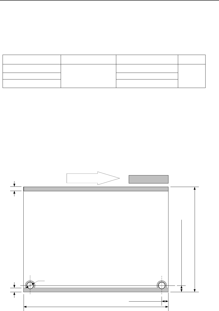
4-7. Applicable PWBs
4-7-1 PWB flow direction
Rightward flow (Transfer PWB from left to right, from the front view)
Leftward flow (Transfer PWB from right to left, from the front view) *
*Note: To be determined at the factory.
4-7-2 PWB sizes and Mass
(1) PWB sizes (Unit: mm)
Minimum size (L
1
x W
1
)
*See Note 1
Maximum size (L
2
x W
2
)
*See Note 1
Thickness T
L-PWB specification
50 x 50
410×360 *See Note 2
0.3 to 4.0 L-Wide-PWB specification 510×360 *See Note 2
XL-PWB specification 610×560 *See Note 2
*Contact us for a notched board or aboard whose shape is irregular.
* A board whose reflectance is low may not be able to be detected with the sensor regardless of its
material and/or color.
Note 1: “L” indicates the dimension in the board transport direction, and “W” indicates the
direction perpendicular with “L.” W/L should be 2 or less.
Note 2: PWB size is extended up to 800 mm for a longer-sized PWB in X axis.
(2) Maximum allowance of PWB mass : 2,000g
(3) Allowable warpage of a PWB
0.2 mm or less per 50 mm area, and 1 mm or less for both upper and lower directions
(these values conform to the JIS B 8461 regulation.)
4-7-3 A range not available to place a component
*1: This is a size at the point of shipment from the factory.
*2: Not required for the shape clamp reference (standard).
Movement of PWB
5 ± 0.1mm *1
(when the diameter of a pin is 4 mm) *2
6mm
3mm
3mm
5 ± 0.1mm
L/;L-Wide - PWB 50 to 360 mm
XL -PWB 50 to 560 mm
L - PWB 50 to 410 mm
L-Wide - PWB 50 to 510 mm
XL - PWB 50 to 610 mm
Marginal areas
- 13 -
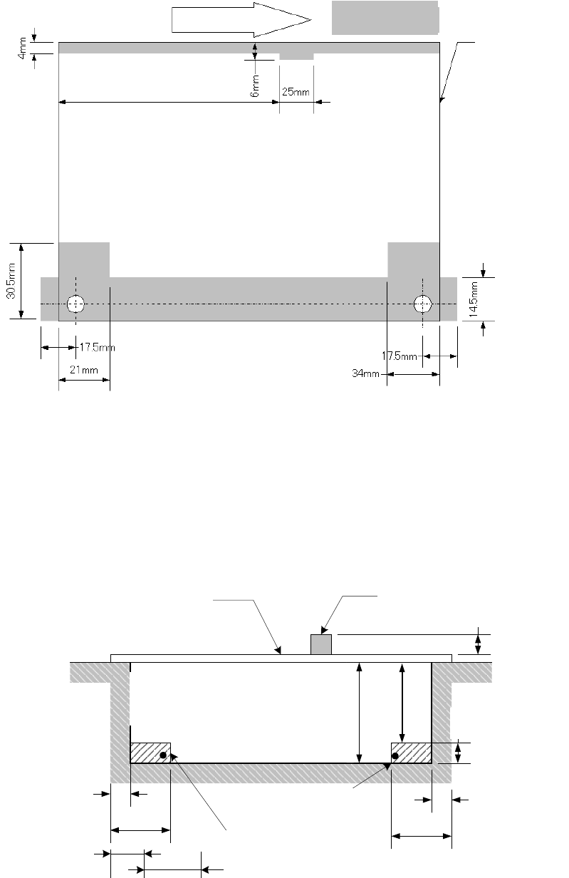
4-7-4 A range not available to set up the support pins
* When a centering pin (optional) is used, the area indicated with a * mark will be limited.
Note1: When the PWB carryout direction is reversed (leftward flow), the range not available to set
up the support pins results in the symmetry of the left and right in the view above.
Note 2: R station in XL-PWB specification results in the symmetry of the left and right in the view
above.
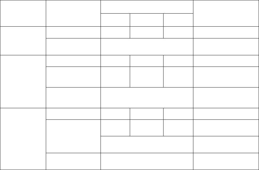
4-7-5 Ranges available to place the components on the PWB front and back
surfaces
基板裏面
搭載可能範囲
6mm
部品
基板
最大40mm
25mm
3mm
ストッパ(固定)
25mm
3mm
10mm
60mm可変(オプション設定時163mm可変)
基準側ストッパ(稼動)
18mm
PWB
Component
Max. 40 mm
Rear of a board
Area on which a component
can be placed
60 mm, variable (163 mm, variable, when an option is set)
Stopper on the reference side
(movable)
Stopper (fixed)
Max. 30mm
Support pin
Marginal areas
Board transportation rails
fixed side
Stopper position
L-PWB
198.5mm
XL-PWB
345 mm
Movement of PWB
*
*
*
*
*
- 14 -
PWB transportation specifications
L/L-Wide -PWB specification : Front fixed or Rear fixed (factory set)
XL -PWB specification : Front fixed only (factory set)
PWBs clamping method
This is a method to use the PWB top surface as a reference to have both the PWB front and
rear ends each at the fixed and movable sides supported to the carryout rails, then, to clamp
the PWBs.
PWB width adjusting methods
Automatic PWB width adjusting method via a motor
(Minimum board size: 50.0 mm × 50.0 mm)
PWB buffer
The conveyor section consist of "three buffers +two stations” which are <IN buffer>, <IN
buffer>, <IN station >, <JOINT buffer>, <OUT station> and <OUT buffer>.
The buffers are limited according to the "X-direction size" of a PWB.
Board
Specifications
X-direction
dimension (mm)
Available buffers
Note
【IN】 【JOINT】
【OUT】
L
410 or less ○ ○ ○ ―
410 to 800
*See Note1
× ―
L-Wide
410 or less ○ ○ ○ ―
410 to 510 ○ × ○ ―
510 to 800
*See Note1
× ―
XL
410 or less ○ ○ ○ ―
410 to 610
○ × ○
Applicable extension
of conveyor
×
Not applicable
extension of conveyor
610 to 800
*See Note1
× ―
○ : available, X : unavailable
Note1: Available when a long-sized board is supported (with the option to be set at the factory).
PWB positioning reference
* Shape reference
* Pin reference (option)