FX-3RA_SPE_EN.pdf - 第46页
- 42 - 9. S A FETY SPECIFICA TION S 9- 1. Standar d Speci fications Emergency stop T wo (2) emer gency stop buttons are instal led on the machine each a t the front and rea r sides. (The one (1) emergency stop button is …
- 41 -
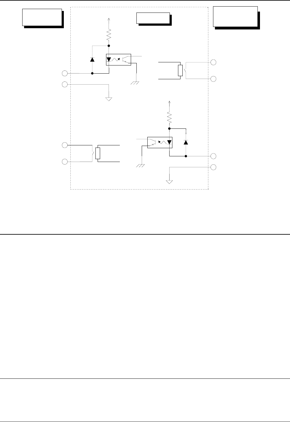
8-2. Interface of the input and Output Signals
8-3. Specifications of the Connecting Cable
Complied with JIS B 8438 Industrial Robots - Electrical Equipment
Cable length: 10m or less
Connector (female) on the main unit
Connector: Tyco Electronics Japan G.K. 206043-1
Pin contact: Tyco Electronics Japan G.K. 66109-4
Connector (male) of the cable
Connector: Tyco Electronics Japan G.K. 206044-1
Pin contact: Tyco Electronics Japan G.K. 170246-1
Clamp: Tyco Electronics Japan G.K. 206070-8
*When you use a JUKI cable with both sides having a connector, note that a connector on the
preproduction/post-production side is male. Therefore, use a female connector of a
preproduction/post-production device
8-4. Data interface
LAN port (10/100 Base-T)
USB2.0
8-5. Utility connections
Piping joint
One-touch connecting plug for theφ8×φ12 hose
Pin No. 1:
Unload enabling input signal
Pin No. 2:
Unload enabling signal Common
Relay contact
Downstream
devices
Main unit
Upperstream
devices
Pin No. 3:
Unload request output signal
Pin No. 4:
Unload request signal Common
Pin No. 1:
Unload enabling output signal
Pin No. 2:
Unload enabling signal Common
Pin No. 3:
Unload request input signal
Pin No. 4:
Unload request signal Common
Relay contact
+24V
+24V
Figure Signal interface and connection terminals
- 42 -
9. SAFETY SPECIFICATIONS
9-1. Standard Specifications
Emergency stop
Two (2) emergency stop buttons are installed on the machine each at the front and rear sides.
(The one (1) emergency stop button is provided when the optional HOD is attached on the
machine.) Depressing these emergency stop buttons immediately stops each axis to cut off
the power supply for driving the motors.
Safety covers
The machine is provided with covers, on the front and rear sides, for both of which the cover
open switch detects either status of opening or closing to suspend the continuous operation
temporarily upon opening either cover or both. Starting the operation as either cover or both
remains at opened, results in a status of low speed operation. Keeping either cover or both
opened results in nullifying both the START and SERVO FREE keys on the operation panel at
the opposite side.
9-2. CE marking specifications
(for EN machine)
This shall comply with the following EC (European Committee) instructions
− EC Machinery Directive : 2006/42/EC
− EC EMC Directive : 2014/30/EU
Applicable standard
Machinery Directive :
EN ISO12100-1:2003, EN ISO12100-2:2003, EN ISO14121-1:2007,
EN ISO13849-1:2008, EN 60204-1:2006, others
EMC Directive:
EN61000-6-4:2007, EN55016-1-2:2004/A1:2005/A2:2006,
EN55016-2-1:2004/A1:2005, EN55016-2-3:2006, EN 61000-6-2:2005,
EN61000-4-2:2009, EN61000-4-3:2006/A1:2008, EN 61000-4-4:2004,
EN61000-4-5:2006, EN61000-4-6:2009, EN61000-4-8:1993/A1:2001

- 43 -
10. RELIABILITY SPECIFICATIONS
10-1. Lifetime of devices
For five (5) years: Excluding either the consumable components or the following regularly
replaceable components.
Refer to the Instruction Manual for the details of consumable components.
− Periodic replacement parts: These must be replaced at intervals of 2 to 3 years as
standard. (The replacement interval varies depending on the operating conditions.)
- Cableveyor - Bear cable assembly
- Air tube
- Solenoid valve
- HOD assembly
- Exhaust filter
- Gas spring
- Filter element
- Battery unit
- Electric feeder IF cable assembly
- Optical fiber cable
- 1394 robot cable assembly
- Tape cutter for electric feeder
- Y-axis roller lubrication component
Criteria for calculating the lifetime:
22 hours per day
300 days per year
Therefore, 22 x 300 x 5 = 33,000 hours/5-years