FX-3RA_SPE_EN.pdf - 第26页
- 22 - 5-2- 12 Pla cement Monitor (Factor y - Set Option) This system provides you the i mages of the picking and the placin g operations during the production. The ultra - miniature camera, w hich is installed on the he…
- 21 -
5-2-8 Solder Recognition Lighting (Factory-set option)
The solder print can be recognized as BOC mark when there is no BOC mark on the PWB or
the circuit.
When the twice-fed long PWB is transported, the placement pad etc. on which the solder
print is performed at the placement of components in the range where the BOC mark is not
prepared can be used as BOC mark.
* Satisfactory placement accuracy might not be obtained in the solder print because shape
as the mark is not clear.
5-2-9 Component Quantity Control (Option)
The lot of the product (PWB) where the components (LED components etc.) are placed is
managed.
When a PWB is loaded, it is checked whether components required to complete a
production of the PWB remain in the feeders with components in different lots not being
mixed in a PWB.
If components are not enough, a warning is displayed before the placement starts.
5-2-10 Connector Bracket (Factory-set option Designed for the Fixed Bank)
This is a unit necessary for connecting devices that requires a power supply such as an
adhesive tape feeder and an IC collection belt to the mounter.
5-2-11 Handheld Operating Device (HOD: Factory-set option)
FX-3RA allows you to check the recognized mark image on the operation screen or perform
various teaching operations. In addition, if an experienced user of any of conventional
mounters does not want to change the operability of the mounter, or if you want to make the
operability of the entire line consistent, you can use the HOD as conventionally.

- 22 -
5-2-12 Placement Monitor (Factory-Set Option)
This system provides you the images of the picking and the placing operations during the
production. The ultra-miniature camera, which is installed on the head, monitors the
operation process and transfers the images to the computer of the placement monitor
system. The system checks the presence or absence of components by comparing the
images before and after the placement. Also, this system allows you to analyze the cause of
an error by viewing the images displayed on the computer.
Features
(1) Function for shooting images of component pick-up/placement
The micro miniature camera takes pictures when a component is picked up and when it is
placed on a board.
An image can be shot for each nozzle.
You can specify whether to shoot an image or not with a production program.
An obtained image can be displayed onto a computer for the Placement Monitor in real
time.
If a communication error occurs, the corresponding error is displayed on the Mounter.
User’s visual check can obtain an optimum parameter, or shorten the time for analyzing
the cause of a trouble.
(2) Trouble cause analyzing tool
Recorded images are linked to the mounter and the computer for the Placement Monitor, and
a database of these images is made.
If any trouble occurs, search through the database allows you to analyze its cause easily.
(3) Setup Assistance
When the current lot is switched to a new one, the optimum pick-up/placement parameters
can be verified.
An image of a component normally placed on a board can be stored onto the database as the
master image, and this image and an image of placement operation being performed during
PWB production can be displayed side-by-side.
(4) Movie mode
Two or more images of a component pick-up operation can be shot, and then displayed
continuously with a computer for the Placement Monitor.
You can select the movie mode: “mode for increasing the number of images that can be shot
by setting the Z-axis speed to ‘Low’” or “mode for repeating picking up two or more
components and rearranging the shot images by setting the Z-axis speed to optional”
(5) Judgment of existence of a component
The function of the Placement Monitor System that automatically judges if a component exists
or not prevents a component placement trouble.
You do not have to enter any parameter for judging existence of a component.
Applicable component sizes:
Minimum size: 0.4×0.2 (mm)
Maximum size: 5.0×5.0 (mm)
Height: 2.0 (mm)
Packaging (feeder) type: Tape feeder
(6) Digital-zooming function
A stored image can be zoomed.
Components from a minute one, 0402 (mm) component are supported, and a shot image of
such a small component is enlarged by default.
(7) Database management
Its simple search function can shorten the time for searching data.
You can conduct database search with various queries.
- 23 -
(8) Board barcode recognizing function (for a barcode/2-D code)
When you use the function for recognizing a barcode or a 2-D code on a board (optional),
you can set the board code in the database of shot images.
Barcode reader assembly
Barcode: The system reads a 1-D barcode on the topside of a board from the upper
section of the board loading entrance.
2-D code: The system reads a 2-D code on the topside of a board with the OCC
attached on the head.
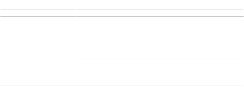
Specifications of the Placement monitor
View field
10.3×6.1mm
Focus height
Board top surface height (0.0 mm)
Focus depth
±
2 mm
Captured images
approximately 200 KB (**.bmp)
approximately 50 to 120 KB (**.png)
(For a single placement component, two photos of pre-pickup
and post-pickup and 2 photos of pre-
placement and
post-placement are taken.) Default value (Note 1)
Approx. 52.8 GB for one hour (Note 2)
(Approx. 200 KB x 4 images x 66,000 CPH) (Pattern IPC9850)
Approx. 6.9 TB for one week (Approx. 52.8 GB x 22 hours x 6
days)
Supported languages
English and Japanese
Destination
Europe, Japan, China and Southeast Asia
* When the placement monitor is used, the placement cycle time of 3% max. becomes slower.
When the “
The system pauses if a component existence error occurs” is used in the placement
monitor setting, the placement cycle time of 40% max. becomes slower.
* When a nozzle No. 505/506 is used, the operation for placing components has been changed
so that the nozzle might not glitter when a photo is taken. As a result, the placement operation
for using nozzle No. 505/506 becomes 18 ms slower per one placement point than that for not
using a placement monitor.
* When the applicable language of the machine proper is Chinese, an application of the
placement monitor is expressed in English.
Note 1: The mode of taking five photos (at placement of components) can be set. When this
mode is actually set up, the placement cycle time becomes a maximum of 35%
slower.
Note2: This capacity is a total of left and right stations (2 computers) in the case where 4
photos are taken for a single placement component.