FX-3RA_SPE_EN.pdf - 第44页
- 40 - 8. INTERF A CE 8- 1. Types and Meanings of Electri cal Signal s over an Electr ical Interface The conceptual diagram o f the electrical signals both on the machines and the other side machines is shown, as fol low…
- 39 -
7. CONTROL SYSTEM
7-1. Saving a program
FX-3RA mounter stores a production program onto the SSD in the main unit.
When you use a USB port, you can store it on an external storage device also.
7-2. Limit of a production program
● Maximum number of placement points per circuit : 10,000 points
● Maximum number of circuits per PWB : 1,200 for a matrix board
200 for a non-matrix board
● Maximum number of points per PWB : 10,000 points
● Maximum number of component data records : maximum number of component
types that can be attached on the machine
● Maximum number of component pick-up records : same as the above.
● Maximum number of Area Fiducial marks :
50 sets for area marks/component placement positioning mark,
1 set for a BOC mark (2 to 3 marks)
7-3. Production Mode
The following three production modes are available during production:
PWB production
- Specifies the number of PWBs you plan to produce and produces PWBs actually.
Trial mode
- Performs a trial PWB production.
You can select the PWB pick-up position tracking function or PWB placement position
tracking function that is to be performed after placement.
Dry run mode
- Checks the PWB pick-up/placement process without using any component.
You can select the PWB pick-up/placement position tracking function.
- 40 -
8. INTERFACE
8-1. Types and Meanings of Electrical Signals over an Electrical
Interface
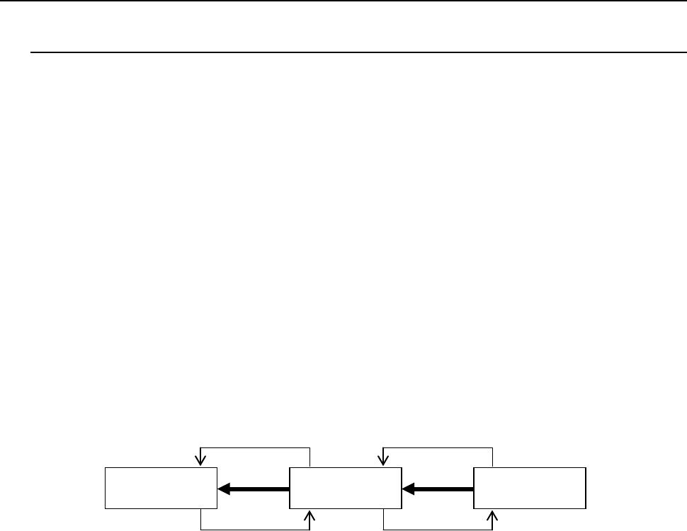
The conceptual diagram of the electrical signals both on the machines and the other side
machines is shown, as follows: The electrical signals between the machines and
upstream-side devices ①, ② and between the machines and downstream-side devices ③,
④is shown in the following diagram.
Electrical signal
①
Unload request input signal (Board Available IN)
This signal receives a PWB unload request from an upstream
device.
Electrical signal
②
Unload enabling output signal (Ready Out)
This signal causes an upstream device to unload a PWB.
Electrical signal
③
Unload request output signal (Board Available Out)
This signal requests a downstream device to unload a PWB.
Electrical signal
④
Unload enabling input signal (Ready In)
This signal receives a PWB unload permission from a downstream
device.
Upper stream
device
Main unit
Down stream
device
①
②
④
③
Figure Conceptual diagram of connection of electrical signals
- 41 -
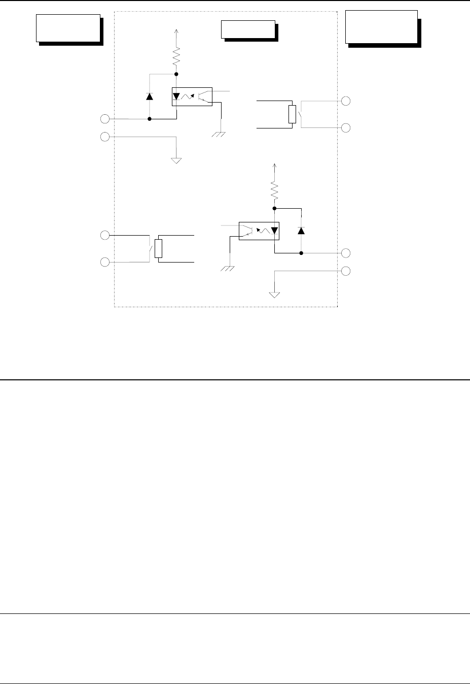
8-2. Interface of the input and Output Signals
8-3. Specifications of the Connecting Cable
Complied with JIS B 8438 Industrial Robots - Electrical Equipment
Cable length: 10m or less
Connector (female) on the main unit
Connector: Tyco Electronics Japan G.K. 206043-1
Pin contact: Tyco Electronics Japan G.K. 66109-4
Connector (male) of the cable
Connector: Tyco Electronics Japan G.K. 206044-1
Pin contact: Tyco Electronics Japan G.K. 170246-1
Clamp: Tyco Electronics Japan G.K. 206070-8
*When you use a JUKI cable with both sides having a connector, note that a connector on the
preproduction/post-production side is male. Therefore, use a female connector of a
preproduction/post-production device
8-4. Data interface
LAN port (10/100 Base-T)
USB2.0
8-5. Utility connections
Piping joint
One-touch connecting plug for theφ8×φ12 hose
Pin No. 1:
Unload enabling input signal
Pin No. 2:
Unload enabling signal Common
Relay contact
Downstream
devices
Main unit
Upperstream
devices
Pin No. 3:
Unload request output signal
Pin No. 4:
Unload request signal Common
Pin No. 1:
Unload enabling output signal
Pin No. 2:
Unload enabling signal Common
Pin No. 3:
Unload request input signal
Pin No. 4:
Unload request signal Common
Relay contact
+24V
+24V
Figure Signal interface and connection terminals