FX-3RA_SPE_EN.pdf - 第18页
- 14 - PWB transportation specifications L/L - W ide - P W B specification : Front fixed or Rear fix ed (factory set) X L - P W B specification : Front fixed only ( factory set) PWBs clamping method Th is i s a met ho d …
- 13 -
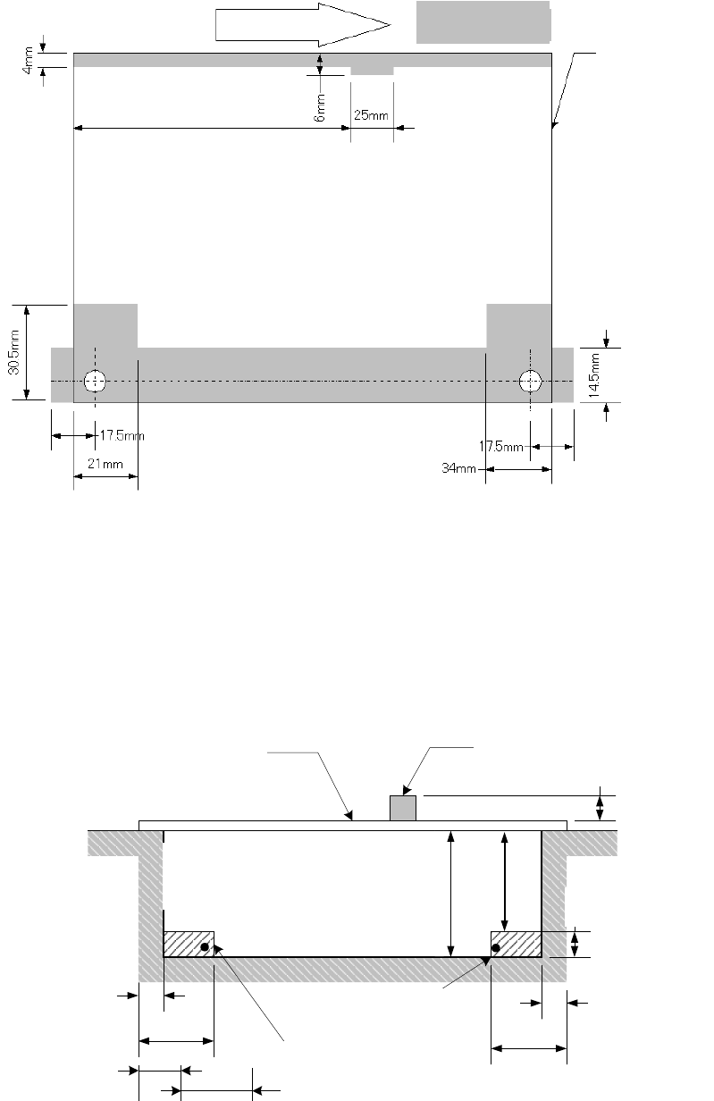
4-7-4 A range not available to set up the support pins
* When a centering pin (optional) is used, the area indicated with a * mark will be limited.
Note1: When the PWB carryout direction is reversed (leftward flow), the range not available to set
up the support pins results in the symmetry of the left and right in the view above.
Note 2: R station in XL-PWB specification results in the symmetry of the left and right in the view
above.
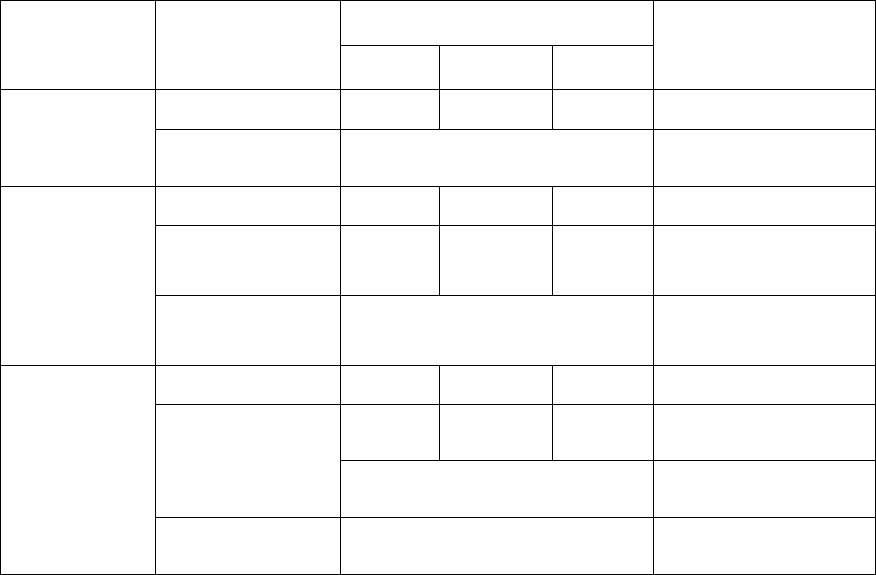
4-7-5 Ranges available to place the components on the PWB front and back
surfaces
基板裏面
搭載可能範囲
6mm
部品
基板
最大40mm
25mm
3mm
ストッパ(固定)
25mm
3mm
10mm
60mm可変(オプション設定時163mm可変)
基準側ストッパ(稼動)
18mm
PWB
Component
Max. 40 mm
Rear of a board
Area on which a component
can be placed
60 mm, variable (163 mm, variable, when an option is set)
Stopper on the reference side
(movable)
Stopper (fixed)
Max. 30mm
Support pin
Marginal areas
Board transportation rails
fixed side
Stopper position
L-PWB
198.5mm
XL-PWB
345 mm
Movement of PWB
*
*
*
*
*
- 14 -
PWB transportation specifications
L/L-Wide -PWB specification : Front fixed or Rear fixed (factory set)
XL -PWB specification : Front fixed only (factory set)
PWBs clamping method
This is a method to use the PWB top surface as a reference to have both the PWB front and
rear ends each at the fixed and movable sides supported to the carryout rails, then, to clamp
the PWBs.
PWB width adjusting methods
Automatic PWB width adjusting method via a motor
(Minimum board size: 50.0 mm × 50.0 mm)
PWB buffer
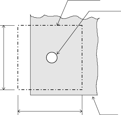
The conveyor section consist of "three buffers +two stations” which are <IN buffer>, <IN
buffer>, <IN station >, <JOINT buffer>, <OUT station> and <OUT buffer>.
The buffers are limited according to the "X-direction size" of a PWB.
Board
Specifications
X-direction
dimension (mm)
Available buffers
Note
【IN】 【JOINT】
【OUT】
L
410 or less ○ ○ ○ ―
410 to 800
*See Note1
× ―
L-Wide
410 or less ○ ○ ○ ―
410 to 510 ○ × ○ ―
510 to 800
*See Note1
× ―
XL
410 or less ○ ○ ○ ―
410 to 610
○ × ○
Applicable extension
of conveyor
×
Not applicable
extension of conveyor
610 to 800
*See Note1
× ―
○ : available, X : unavailable
Note1: Available when a long-sized board is supported (with the option to be set at the factory).
PWB positioning reference
* Shape reference
* Pin reference (option)
- 15 -
4-7-6 Function correcting the PWB positions
Field of vision for recognizing the reference marks
□6.3 mm (camera’s field of vision for recognition).
Window size for recognizing the reference marks
This size can be adjusted within the maximum 6.3 mm-area, subject to securing a clearance
between the recognition mark and its surrounding area.
Kinds of recognition marks and corrective method
- PWB reference mark
Two or three marks are located on a PWB to correct the entire PWB.
When a machine detects two PWB reference marks, it corrects the positioning, angle and
expansion/contraction of the entire PWB. When detecting three PWB reference marks,
it corrects the perpendicularity in the X and Y direction also.
- Marks used to position the component area
Two marks (their positions can be set as you like) are to be provided to a group of
components placement positions, and they are used to correct each component
placement position in the group (Up to 50 sets of marks).
Note 1: The position is arbitrary, subject to not aligning three (3) reference makes,
if this is the case, on one (1) straight line. (It is recommended that the reference
marks should be made at the four (4) corners of the PWBs
Note 2: PWB reference marks in two or three positions (four or six positions in total), which
can be detected every time when the PWB is fed, are necessary by split clamping
PWB transport that is an option to a longer sized PWB in X axis.
Figure Field of vision for recognizing the reference marks
PWB
Field of vision for PWBs recognition
Recognition mark
6.3mm
6.3mm