FX-3RA_SPE_EN.pdf - 第43页
- 39 - 7. CONTROL SYSTEM 7- 1. Saving a progr am FX - 3R A mounter stores a produc tion program onto the SSD in the main u nit. W hen y ou us e a USB po r t, you can store it on an external storage device also. 7- 2. Lim…
- 38 -
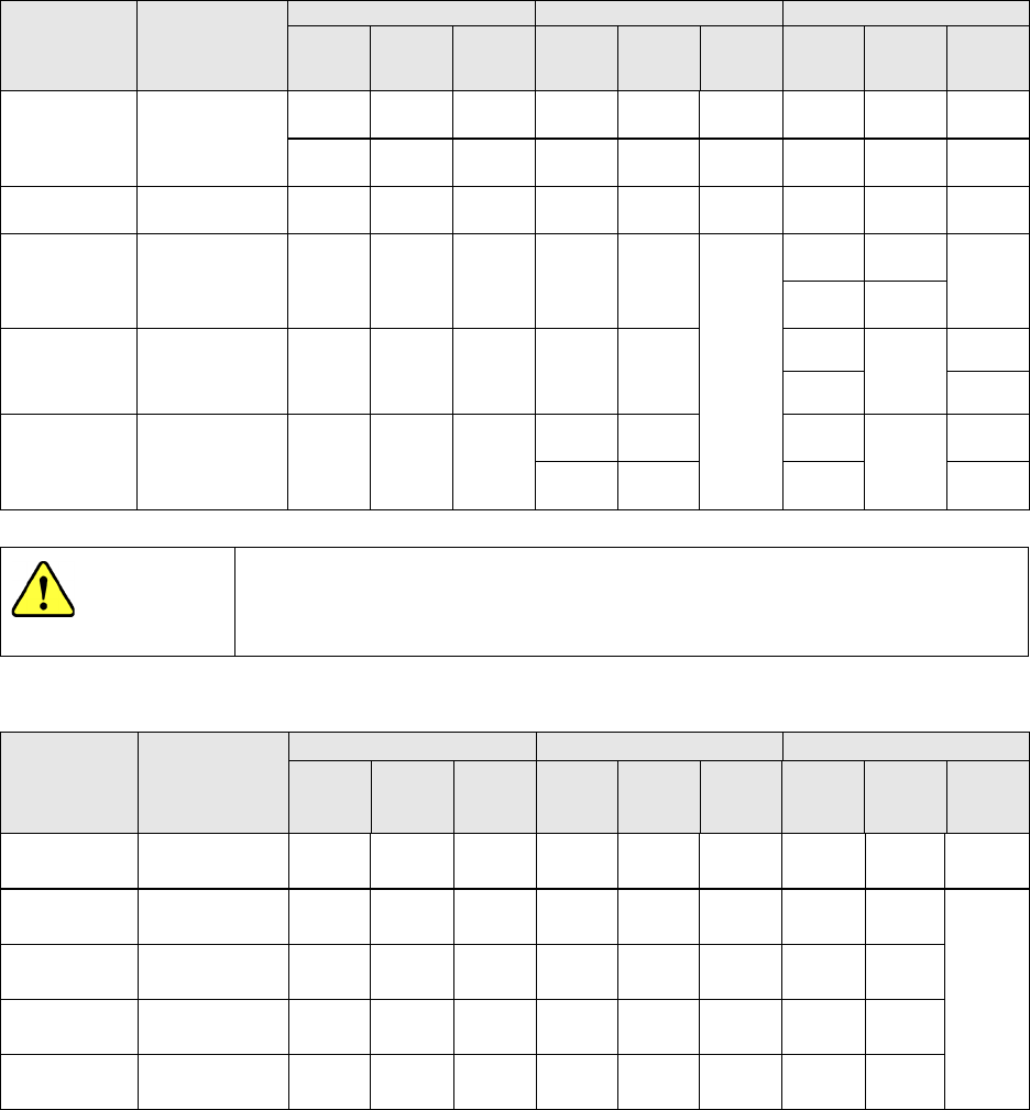
Stick feeder for mechanical bank
・Feeder type: Type N (SFN*AS)
Model Lane width [mm]
SOP
SOJ
PLCC(QFJ)
Nominal
size
[mil]
Element
width
[mm]
Element
height
[mm]
Nominal
size
[mil]
Element
width
[mm]
Element
height
[mm]
Nominal
size
[mil]
Element
width
[mm]
Element
height
[mm]
SFN0AS
(Type N0)
At delivery:
6.9
Adjustment range:
6.6~9.2
225
5.72
~
6.99
~1.5
300
7.62
~
8.89
2.0
SFN1AS
(Type N1)
7.2 225
5.72~
6.99
1.5
SFN2AS
(Type N2)
9.2 300
7.62~
8.89
2.0 300
8.38~
8.76
3.25~
3.76
285×
425
8.05
~
8.31
4.20~
5.08
290×
490
8.13~
8.51
SFN3AS
(Type N3)
11.2 375
9.35~
10.8
2.5 350
9.65~
10.03
350
9.78~
10.03
4.20
~
4.57
350×550
4.20~
5.08
SFN4AS
(Type N4)
13.0 450
11.43~
12.7
3.0
400
10.92
~
11.30
450
12.32~
12.57
4.20~
4.57
450
12.19~
12.57
450×
550
4.20~
5.08
Use a dedicated stick feeder matched to each element size. Otherwise,
elements may be broken due to inaccurate operation even if they are
caused to flow.
・Feeder type: Type W (SFW*AS)
Model
Lane width
[mm]
SOP
SOJ
PLCC(QFJ)
Nominal
size
[mil]
Element
width
[mm]
Element
height
[mm]
Nominal
size
[mil]
Element
width
[mm]
Element
height
[mm]
Nominal
size
[mil]
Element
width
[mm]
Element
height
[mm]
SFW1AS
(Type W1)
15.0 525
13.34~
14.61
3.5
SFW2AS
(Type W2)
18.2 600
15.24~
16.51
4.0 650
17.40~
17.65
4.20~
5.08
SFW3AS
(Type W3)
20.8 750
19.94~
20.19
SFW4AS
(Type W4)
26.0
950
25.02~
25.27
SFW5AS
(Type W5)
31.2
1150
30.1~
30.55
- For Types N1 to N4 and types W1 to W5, an optional spacer kit is available for a change to another type.
- Type N0, the clearance can be finely adjusted by attached spacer to secure the lane width for SOP 8 pins and
10 pins.
CAUTION

- 39 -
7. CONTROL SYSTEM
7-1. Saving a program
FX-3RA mounter stores a production program onto the SSD in the main unit.
When you use a USB port, you can store it on an external storage device also.
7-2. Limit of a production program
● Maximum number of placement points per circuit : 10,000 points
● Maximum number of circuits per PWB : 1,200 for a matrix board
200 for a non-matrix board
● Maximum number of points per PWB : 10,000 points
● Maximum number of component data records : maximum number of component
types that can be attached on the machine
● Maximum number of component pick-up records : same as the above.
● Maximum number of Area Fiducial marks :
50 sets for area marks/component placement positioning mark,
1 set for a BOC mark (2 to 3 marks)
7-3. Production Mode
The following three production modes are available during production:
PWB production
- Specifies the number of PWBs you plan to produce and produces PWBs actually.
Trial mode
- Performs a trial PWB production.
You can select the PWB pick-up position tracking function or PWB placement position
tracking function that is to be performed after placement.
Dry run mode
- Checks the PWB pick-up/placement process without using any component.
You can select the PWB pick-up/placement position tracking function.
- 40 -
8. INTERFACE
8-1. Types and Meanings of Electrical Signals over an Electrical
Interface
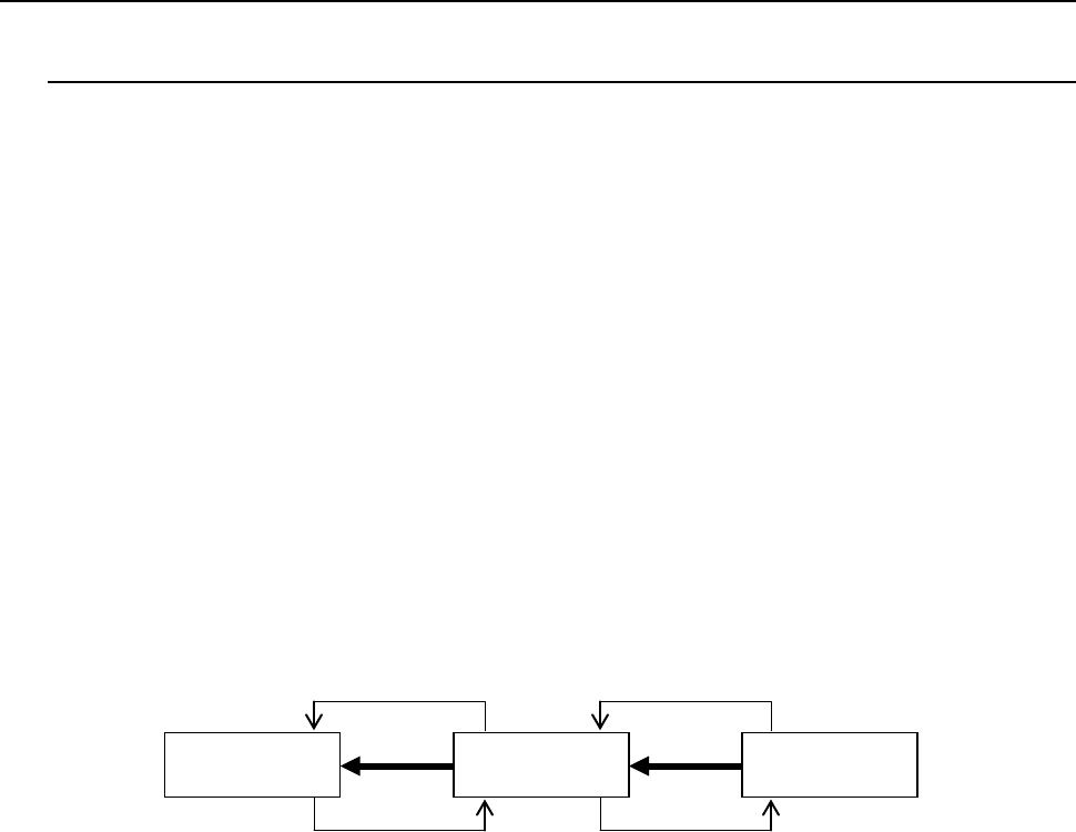
The conceptual diagram of the electrical signals both on the machines and the other side
machines is shown, as follows: The electrical signals between the machines and
upstream-side devices ①, ② and between the machines and downstream-side devices ③,
④is shown in the following diagram.
Electrical signal
①
Unload request input signal (Board Available IN)
This signal receives a PWB unload request from an upstream
device.
Electrical signal
②
Unload enabling output signal (Ready Out)
This signal causes an upstream device to unload a PWB.
Electrical signal
③
Unload request output signal (Board Available Out)
This signal requests a downstream device to unload a PWB.
Electrical signal
④
Unload enabling input signal (Ready In)
This signal receives a PWB unload permission from a downstream
device.
Upper stream
device
Main unit
Down stream
device
①
②
④
③
Figure Conceptual diagram of connection of electrical signals