FX-3RA_SPE_EN.pdf - 第15页
- 11 - 4- 5. Applicabl e Component 4-5-1 A pplic able compone nt sizes Unit =mm Recognition dev ice FX - 3R A Length × W i dth LNC60 /61 Minimum: 0 .4 x 0. 2 Max imum: □33.5 (Length of a side: 35 ) <See Note 1 .> C…
- 10 -
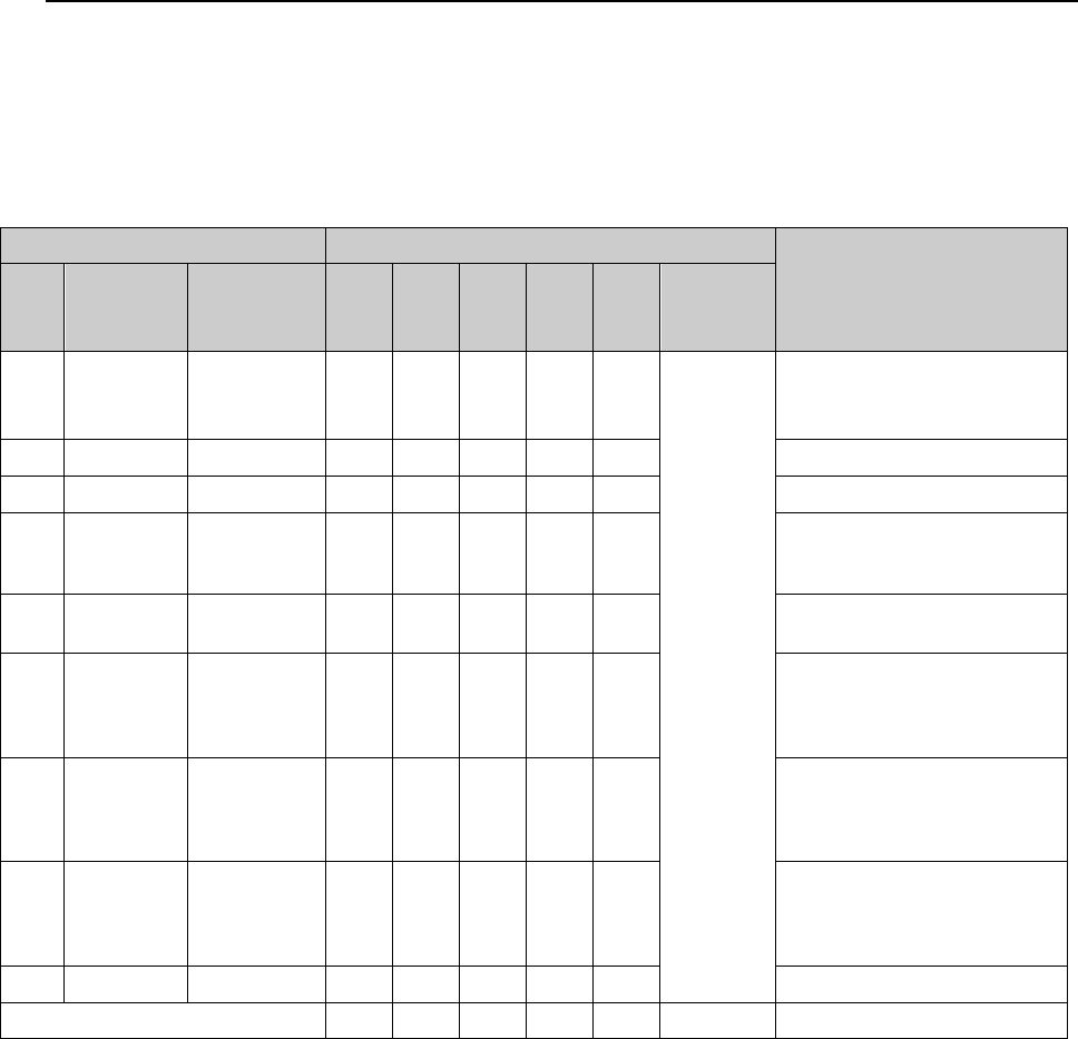
4-4. Nozzles
Various types of nozzles have been designed to increase the reliability of placement of each
type of components as shown in the table below. Nozzles whose number is from 500 to 509
are used for both laser recognition of components and vision
You can select one of the nozzle sets shown in Table as the standard nozzles supplied with
FX-3RA products.
Table Nozzles supplied as the standard devices
Nozzle Nozzle assembly
Applicable components
(reference) and remarks
NO.
Internal
diameter
of a nozzle
External
diameter of
a nozzle
A B D E F
Std.
Nozzle
slection
500
2-φ0.4
1.0 x 0.5 - 24 - - 18
Note.1
1005, 1608, 2012
*See
Note 2
SOT (Molding: 1.6 x 0.8)
501
φ0.25
0.7 x 0.4 - - - 18 18 0603
502
φ0.4 φ0.7
24 - 24 24 1005
503
φ0.6 φ1.0
24 - 18 12 -
1608, 2012,
SOT (Molding: 1.6 x 0.8),
SOT (Molding: 2.0 x 1.25)
504
φ1.0 φ1.5
- 12 12 6 6
2012, 3216, SOT23, SOT
(Molding: 2.0 x 1.25)
505
φ1.7 φ3.5
4 4 4 2 2
Aluminum electrolytic
capacitor
(small), tantalum electrolytic
capacitor, trimmer
506
φ3.2 φ5.0
4 - 2 - -
Aluminum electrolytic
capacitor (medium),
SOP (narrow type),
SOJ, Connector
507
φ5.0 φ8.5
4 - - - -
Aluminum electrolytic
capacitor (large),
SOP (wide type),
TSOP, QFP, PLCC, Connector
508
φ8.0 φ9.5
4 4 4 4 4 QFP, PLCC, BGA
Total number of nozzles 64 44 64 66 48 44
* Nozzles other than the supplied ones are optional.
* A nozzle assembly for a CVS is provided with the same number of nozzles.
* Total number of nozzles that can be installed onto an ATC station: 72. (18 nozzles for one
unit × 4 units)
Note1: As a set of standard nozzles (descried in the column “Std. Nozzles selection” above), you
can select 44 nozzles among those whose number is from 500 to 508C.
However, you have to select a nozzle to be used for calibration of the machine:
・ For laser calibration (one of the nozzles:500, 502 and 503)
・ For image calibration (508 nozzle)
Note 2: Since a theta error may occur due to the shape of the surface of a 2012R component to be
picked (such as differences of manufactures and/or resistance values), use a No. 504
nozzle if you have to place 2012R components in the high density (the gap between the
adjacent components: 0.3 mm or less).
- 11 -
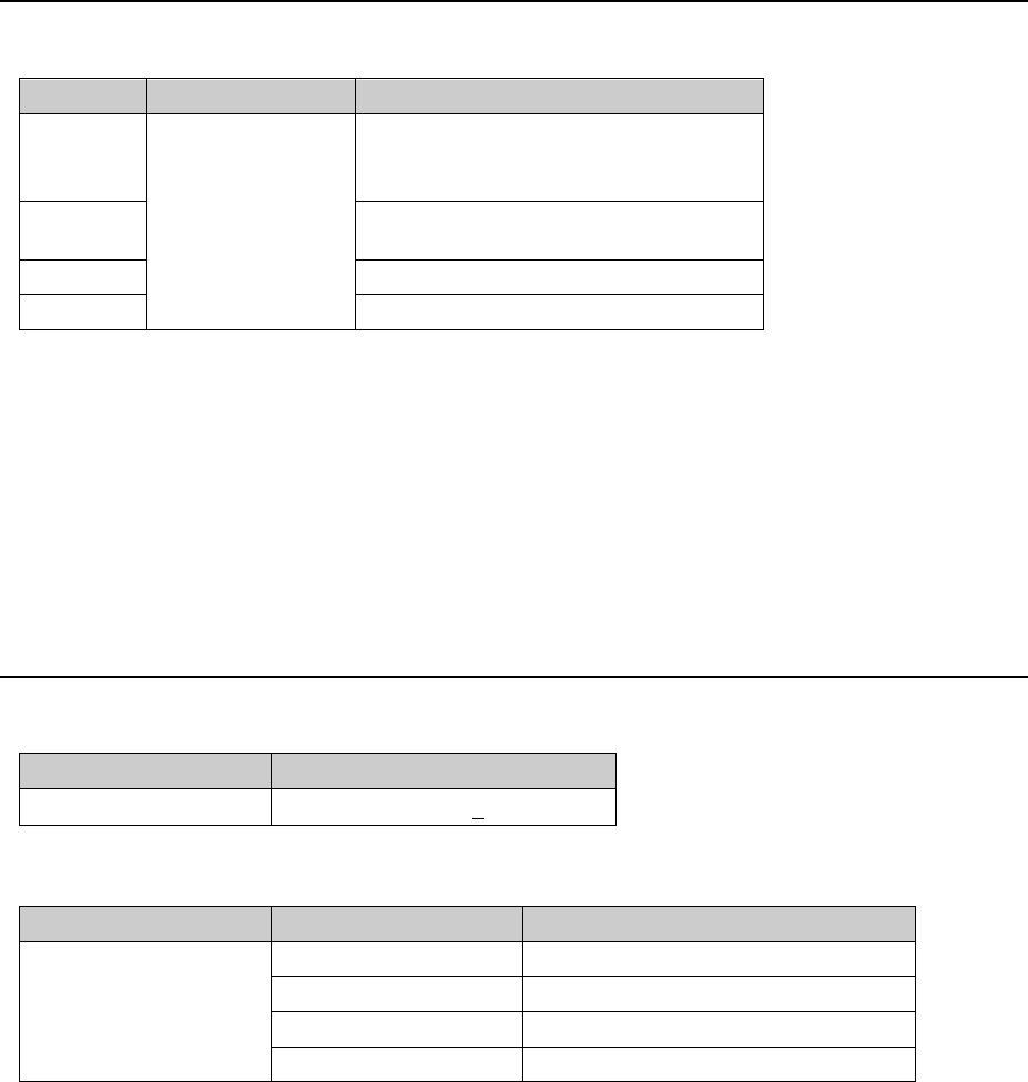
4-5. Applicable Component
4-5-1 Applicable component sizes
Unit=mm
Recognition device FX-3RA
Length
×
Width
LNC60/61
Minimum: 0.4 x 0.2
Maximum: □33.5
(Length of a side: 35 ) <See Note 1.>
Component
height
0.08 (for a 0402 component) to 6.0
Lead pitch
0.65 or more <See Note 2. >
Ball pitch
1.00 or more <See Note 2. >
Note 1: The maximum size of components that can be recognized with 6 nozzles of the
LNC60/61 at the same time is □ 10.0 mm.
When you are to place components whose size is more than □ 10.0 mm with the
LNC60/61 head, only three heads are used to pick them up.
For placement of element 0402, a dedicated tape feeder as well as nozzle 509 is
required.
Note 2: Neither a lead section nor a ball section can be recognized with laser.
4-6. Component Placement Accuracy at X, Y and
θ
Placed positions (X, Y)
Unit=μm
Component name
Component placement accuracy
Square chip
± 50 (Cpk ≥ 1)
Placed posture (
θ
) (Unit: degrees)
Component name
Size Laser recognition device LNC60/61
Square chip
0402 ±5.0
0603 ±3.0
1005 ±2.5
1608 or larger ±2.0
Adjacent pitch
- 0402: 0.15mm
- 0603, 1005: 0.20mm
- 12 -
4-7. Applicable PWBs
4-7-1 PWB flow direction
Rightward flow (Transfer PWB from left to right, from the front view)
Leftward flow (Transfer PWB from right to left, from the front view) *
*Note: To be determined at the factory.
4-7-2 PWB sizes and Mass
(1) PWB sizes (Unit: mm)
Minimum size (L
1
x W
1
)
*See Note 1
Maximum size (L
2
x W
2
)
*See Note 1
Thickness T
L-PWB specification
50 x 50
410×360 *See Note 2
0.3 to 4.0 L-Wide-PWB specification 510×360 *See Note 2
XL-PWB specification 610×560 *See Note 2
*Contact us for a notched board or aboard whose shape is irregular.
* A board whose reflectance is low may not be able to be detected with the sensor regardless of its
material and/or color.
Note 1: “L” indicates the dimension in the board transport direction, and “W” indicates the
direction perpendicular with “L.” W/L should be 2 or less.
Note 2: PWB size is extended up to 800 mm for a longer-sized PWB in X axis.
(2) Maximum allowance of PWB mass : 2,000g
(3) Allowable warpage of a PWB
0.2 mm or less per 50 mm area, and 1 mm or less for both upper and lower directions
(these values conform to the JIS B 8461 regulation.)
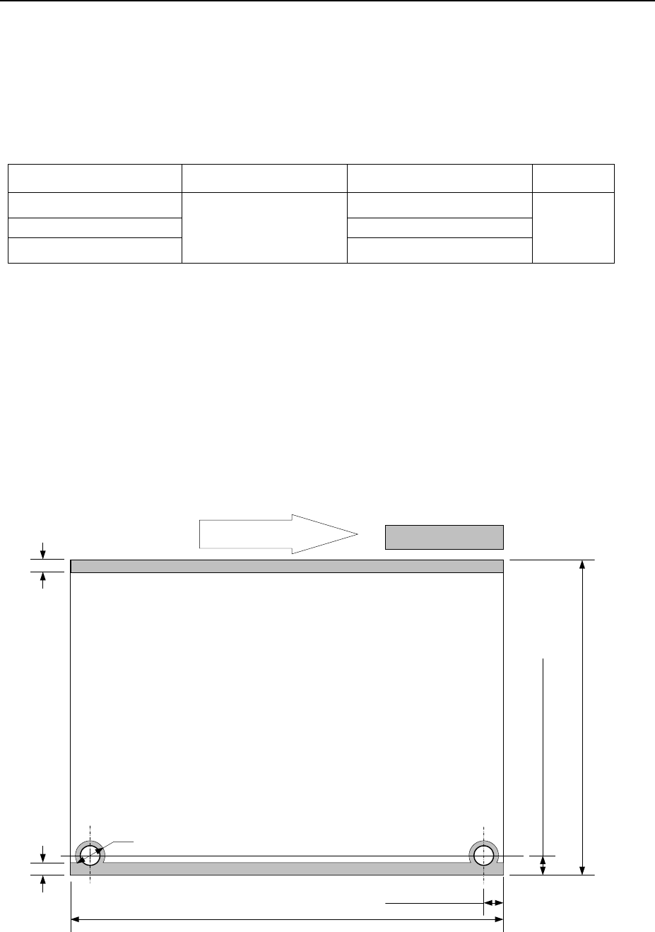
4-7-3 A range not available to place a component
*1: This is a size at the point of shipment from the factory.
*2: Not required for the shape clamp reference (standard).
Movement of PWB
5 ± 0.1mm *1
(when the diameter of a pin is 4 mm) *2
6mm
3mm
3mm
5 ± 0.1mm
L/;L-Wide - PWB 50 to 360 mm
XL -PWB 50 to 560 mm
L - PWB 50 to 410 mm
L-Wide - PWB 50 to 510 mm
XL - PWB 50 to 610 mm
Marginal areas