FX-3RA_SPE_EN.pdf - 第38页
- 34 - 6-3-4 Tape feeder f or el ectric b ank The electrical tape feeder , ETF , can feed components m ore stably without being af f ected by vibration since a motor drives it. In addition, E TF allows y ou to splice the…

- 33 -
② FTFR (32 mm, 44 mm, and 56 mm)
Product code Feed pitch
Pick
position
(Y direction)
Applicable
component
emboss width
Applicable
component
emboss
depth
FF323R 12 mm
132 mm
23.5 mm or less
25 mm or
less
FF324R
16 mm
FF32FR 8/12/16/20/24 mm
FF32FR-OP 8/12/16/20/24/28/32 mm 114 mm
FF443R
12 mm
128 mm
33.8 mm or less
FF444R 16 mm
FF44FR 8/12/16/20/24 mm
FF44FR-OP 8/12/16/20/24/28/32/36/40/44 mm 114 mm
FF564R 12/16 mm 128 mm
46.0 mm or less
FF568R 12/16/20/24/28/32 mm 114 mm
FF56FR 8/12/16/20/24 mm 128 mm
FF56FR-OP 8/12/16/20/24/28/32/36/40/44/48/56 mm 114 mm
Dimensions
L =693 mm, H =472 mm
W= FTFR32**:47.7 mm, FTFR44**:61.6 mm, FTFR56**:66.0 mm
Mass
(Excluding a
reel)
FTFR32**:3.2 kg, FTFR44**:3.5 kg, FTFR56**:3.8 kg
Component
transport
method
Ratchet drive system
* For the component size or tape specifications, follow the JIS C0806-3:1999, IEC
60286-3:2007.
* RFID compliance is necessary when you use production control system. .
(2) Options
① Emboss spacer (FTFR only)
When the component width and length are large and the tape depth is small, the posture
stability at component pickup can be improved by placing the spacer at the component
pickup position of the tape feeder.
The usable emboss depth is 1.0 mm to 8.0 mm.
② RFID tag attachment kit
By attaching a RFID tag on a FTF/FTFR feeder currently used, you can manage the
feeders with production management system.
* RFID tag cannot be attached on the old type of the FTF feeder.
For further advice, contact JUKI or the representative office in your area.
- 34 -
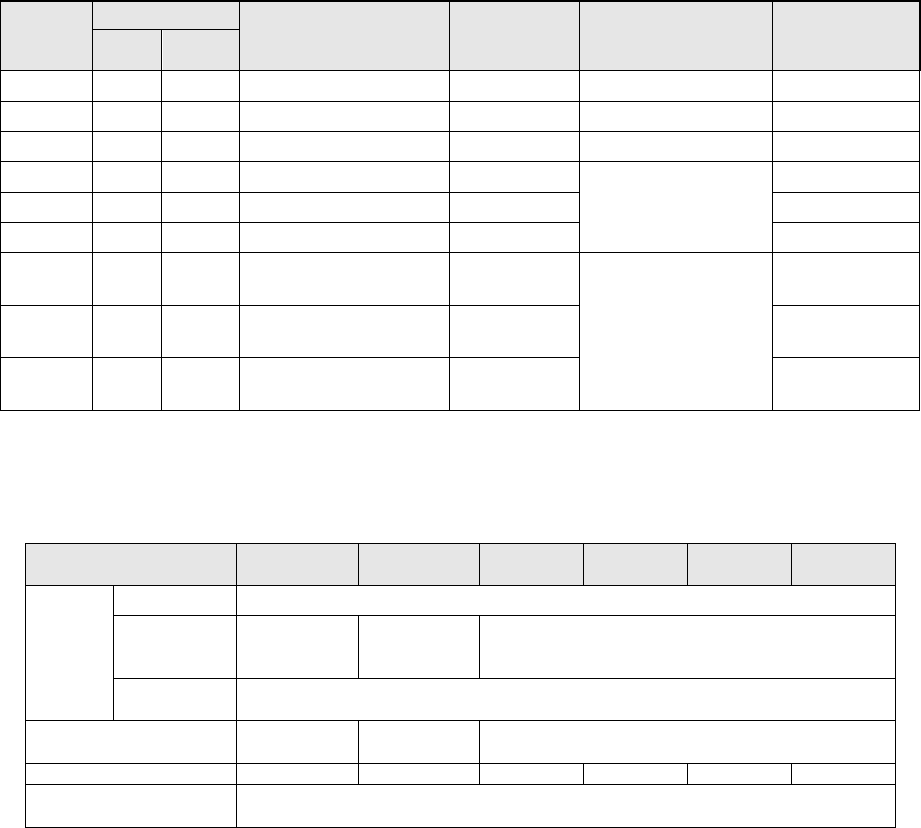
6-3-4 Tape feeder for electric bank
The electrical tape feeder, ETF, can feed components more stably without being affected by
vibration since a motor drives it. In addition, ETF allows you to splice the component tape
and to change the feed pitch easily; which provides the higher feeder utilization rate
compared with the existing mechanical feeder.
(1) Component specifications
Product
code
Tape type
Feed pitch
Applicable
components
Width
Applicable
component emboss
depth
Remarks
Paper Emboss
EF02HS
○ -
2mm
8mm
None
0402
~
1005
EF08HS
○ ○
2/4mm 8mm 3.5mm or less
0603~
EF08HD
○ ○ 2/4mm 8mm×2 3.5mm or less 0603~
EF12FS
- ○
4/8/12mm
12mm
12.5 mm or less
(17mm or less)
EF16FS
-
○
4/8/12/16mm
16mm
EF24FS
-
○
4/8/12/16/20/24mm
24mm
EF32FS
- ○
4/8/12/16/20/24/28/
32mm
32mm
12.5 mm or less
(26mm or less)
EF44FS
- ○
4/8/12/16/20/24/
28/32/36/40/44mm
44mm
EF56FS
- ○
4/8/12/16/20/24/28/32/
36/40/44/48/52/56mm
56mm
* Use components with specifications that conform to JIS C0806-3: 1999, IEC 60286-3:2007.
* RFID compliance is necessary when you use production control system.
* Up to 12.5 mm is supported as the depth of an embossed section of a component.
(2) Common specifications
(3) Option
① Tape cutting jig (A type, B type)
A positional adjustment between the tape feeder under production and the tape feeder
to be connected can be accurately and quickly made by cutting the tape with dedicated
scissors at connection of tape.
A type : Feeding pitch 4,12,20,28,36,44,52
B type : Feeding pitch 8,16,24,32,40,48,56
② Joint tape
This is a tape that splices an old tape reel and a new tape reel.
A dedicated type for each tape width is available.
③ RFID tag attachment kit
By attaching a RFID tag on a ETF feeder currently used, you can manage the feeders
with production management system.
EF08HS
EF02HS
EF08HD EF12FS
EF16FS
EF24FS
EF32FS
EF44FS
EF56FS
Power
supply
Voltage DC24V
Maximum
allowable
current
1.8A 2.1A 1.8A
Stand by
current
130mA
Dimensions (mm)
L=660mm
H=335mm
L=911mm
H=455mm
L=700mm
H=335mm
Mass (kg)
2.5kg
3.0kg
3.0kg
3.5kg
4.0kg
4.5kg
Component feeding
system
Electrical motor drive system
- 35 -
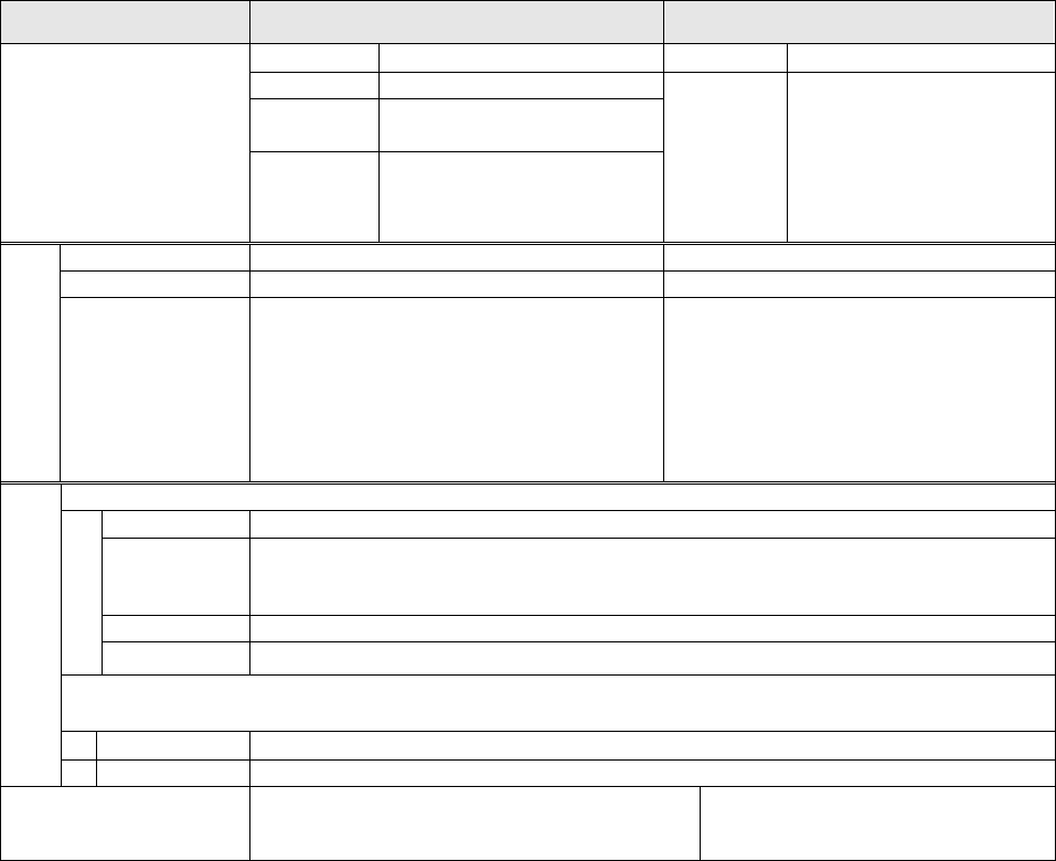
6-3-5 Feeder calibration jig with LCD monitor
This Jig is for calibrating a feeder while monitoring the component pick-up position with a
CCD camera. If you check and calibrate the pick position on a regular basis, you can
maintain the stable pick-up capability.
On support of production management system. *Only production management system for a
mechanical feeder (JM01) is available.
As an option, if you attach the RFID reader (antenna) onto the jig main unit, you can
manage the maintenance state of each feeder with the production management system,
which records the maintenance history, the frequency of usage and others for each
feeder; For example, the system indicates a feeder of which pick-up ratio became lower,
and displays a list of feeders that need to be calibrated according to the maintenance
interval settings.
* To use “Intelli feeder calibration Jig with LCD monitor, “production management
system” is required.
For details, refer to "Equipment Specifications of Production Management System"
Note 1: A jig tape and tools are required separately when adjust feeder.
Note 2: RFID compliance is necessary when you use production control system.
For Mechanical Feeder(JM01) For Electric Feeder (EFATG)
Feeders
*See Note1
ATF
8mm to 24mm *Note2
ETF
8mm
~
56mm
CT F,CTFR
8mm *Note2
- -
FTF
FTFR
8mm to 72mm *Note2
32mm to 56mm *Note2
BF
BF10AS,BF11AS,
BF12BS,BF12CS,
BF25CS,BF28CS,BF28RS
Specifications
Power supply
Select 100 V - 120 V or 200 V - 240 V
100 - 240V
Outer dimension
L=290mm , H=480mm, W=157mm
L=400mm , H=710mm, W=240mm
Mass
- Adjustment jig main unit: 12 kg or less
(including the CCD camera and lens
section)
- Master feeder: 2 kg
- Monitor: 4kg
- Adjustment jig main unit: 20 kg or
less
(including the CCD camera and
lens section)
- Master feeder: 3.5 kg
- Monitor: 4 kg
- Power supply: 2.5kg
Environment
During operation
Temperature
10°C to 35°C
Accuracy
guaranty
temperature
20°C to 25°C
Humidity
30% to 80%RH (No condensation)
Altitude
1,000m or less
Transportation or storage
Temperature
-15°C to 70°C
Humidity
20% to 95%RH (No condensation)
Option for production
management system
Options for the RFID system
- Controller (MPC) - Antenna
-