FX-3RA_SPE_EN.pdf - 第23页
- 19 - 5-2-2 Fe eder Trolle y Exchange Function (Factory - Set Option) By using a feeder trolley , t his function allow s a group of feeders to be attach ed or remove d onto/from the main unit at a time. Since this funct…
- 18 -
5. STANDARD FUNCTIONS AND OPTIONAL
FUNCTIONS
5-1. Standard Functions
5-1-1 Height Measurement System (HMS)
When preparing the pick data, the component pick position and height shall be measured via
the laser sensors. For a component whose pick-up plane is transparent like glass (LED, etc.),
a component like a mirror that reflects light almost 100%, a component that is blue, and a
component that is less than 0603, this function is not applicable. The function can also be
used as a teaching spot.
5-1-2 Vacuum pump
This pump allows the machine to reduce air consumption of the compressor, and improve
the stability of air supply when it picks up a component.
5-1-3 Feeder Float Detecting Sensor
This function is provided to prevent mechanical troubles caused by improper installation of
tape or stick feeders. When this sensor detects an improperly-installed feeder, it stops the
X-Y axes, and warns an operator.
5-2. Option
5-2-1 Bad Mark Reader (BMR, Factory-Set Option)
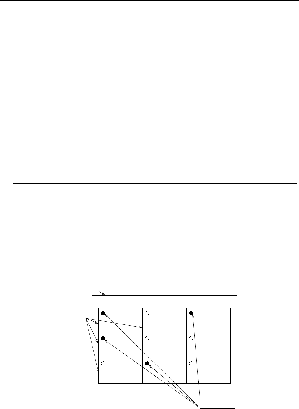
A bad mark (bad circuit) is given to each circuit on a multi-circuit PWB to prevent any
component from being placed on the circuit.
The minimum diameter of a bad mark is φ2.5 mm or more and the color of a mark should be
highly contrasted with that of a board. The brightness can be switched when the difference
between the color of a board and the amount of light reflected from the mark is enough.
When you use an optional bad mark reader, the time for recognizing one bad mark can be
shortened by approximately 0.1 seconds with comparing with the time taken with the
standard OCC.
バ ッ ド マ ー ク
グ ロ ー バ ル バ ッ ド マ ー ク
基 板
回 路
Board
Circuits
Bad marks

- 19 -
5-2-2 Feeder Trolley Exchange Function (Factory-Set Option)
By using a feeder trolley, this function allows a group of feeders to be attached or removed
onto/from the main unit at a time. Since this function enables changeover from the current
feeders to the next feeders even during production of PWBs, it shortens the time required for
changeover.
Note: There are two different types of feeder exchange trolleys, for the electrical and the
mechanical feeders. They cannot be attached together on the same trolley. Use the
suitable trolley for each. Also, the special tape cutter is to be attached to the trolley for
the electrical feeders.
5-2-3 Rear Side Operation Unit (Factory-Set Option)
The liquid crystal display monitor, keyboard and mouse are attached on the rear of the main
unit allows you to perform the same operation as that of the front operation unit (this
operation unit is equipped with the front/rear operation switch).
5-2-4 Components verification System (CVS, Factory-Set Option)
This function is provided to inspect components to be placed before production and at the
restart after components run out, and detect errors such as component, polarity, feeder
setting position and other errors in advance. Up to six components are checked at the same
time.
Components applicable to this check:
Applicable component type
- Square chip
- Laminated ceramic capacitor
- Tantalum chip capacitor
- Aluminum electrolytic capacitor
- Chip film capacitor
- 2-pin diode
Inspection conditions
- Component that have two electrodes: one on the bottom and
another on the opposite side
- Component whose electrode distance is 10 mm or less
- Component whose external dimensions are □ 10.00 mm or less
- For a single measurement, a 0402 component or larger
components
- For simultaneous measurement, a 1005 component or larger
components (The longer side shall be 0.95 mm or longer.)
* Diodes are limited to general commutating diodes (other than light-emitting diodes and
zener diodes).
Check items
1) Resistance value Measurement range: 10 Ω to 1 MΩ
Measurement accuracy: ± 5 %
2) Electrostatic capacitance Measurement range:100 pF to 100 μF
Measurement accuracy: ± 20 %
3) Diode polarity Measurement range: Forward voltage 1.8 V or less
Open voltage 0 to 4.3 V or less
Nozzle
The following nozzles exclusively designed for the CVS are required to use the verification
function.
Standard nozzles: 500CVS, 501CVS,502CVS, 503CVS, 504CVS, 505CVS,509CVS

- 20 -
5-2-5 Feeder Indicator Function (FPI, Factory-Set Option)
This function uses LEDs to notify an operator of the feeder position to be checked if the
stocked components run out or an feeder error occurs during production of PWBs. This
feature shortens the time spent for replacing a feeder and improves the operability of the
KE-2000 series of products.
5-2-6 SOT Direction Check Function (Factory-Set Option)
This function uses the OCC to check the component supply angle by placing a 3-terminal
SOT component on the SOT direction check table before production or the restart after
components run out.
Applicable components:
- Component dimensions: 1.6 mm to 4.0 mm x 4.0 mm
- Electrode dimensions: Length 0.2 mm to 1.0 mm
Width 0.1 mm to 1.0 mm
5-2-7 Longer sized PWB in X axis (Factory-set option)
The PWB size in the X-direction can be extended up to 800 mm by split clamping system
with HMS. As a result, the production of a long PWB used for the LED lighting etc. is enabled.
(Shape reference only)
Sizes of handling a long PWB: (Unit: mm)
Direction
Minimum
size
Maximum size
Standard-
clamping
Split
clamping
L-size specification
X 50 410 800
Y 50 360
L-Wide size
specification
X 50 510 800
Y 50 360
XL-size specification
X 50 510 800
Y 50 460