1_NXT Conveyor(1.0)E.pdf - 第11页
8. If it was out of tolerance loosen the 22mm nut and use a 14mm spanner to rotate the shaft and set the flatness. If there is a difference between the reference and secondary rail, loosen the 10mm nut and move the cente…
・ Rear side
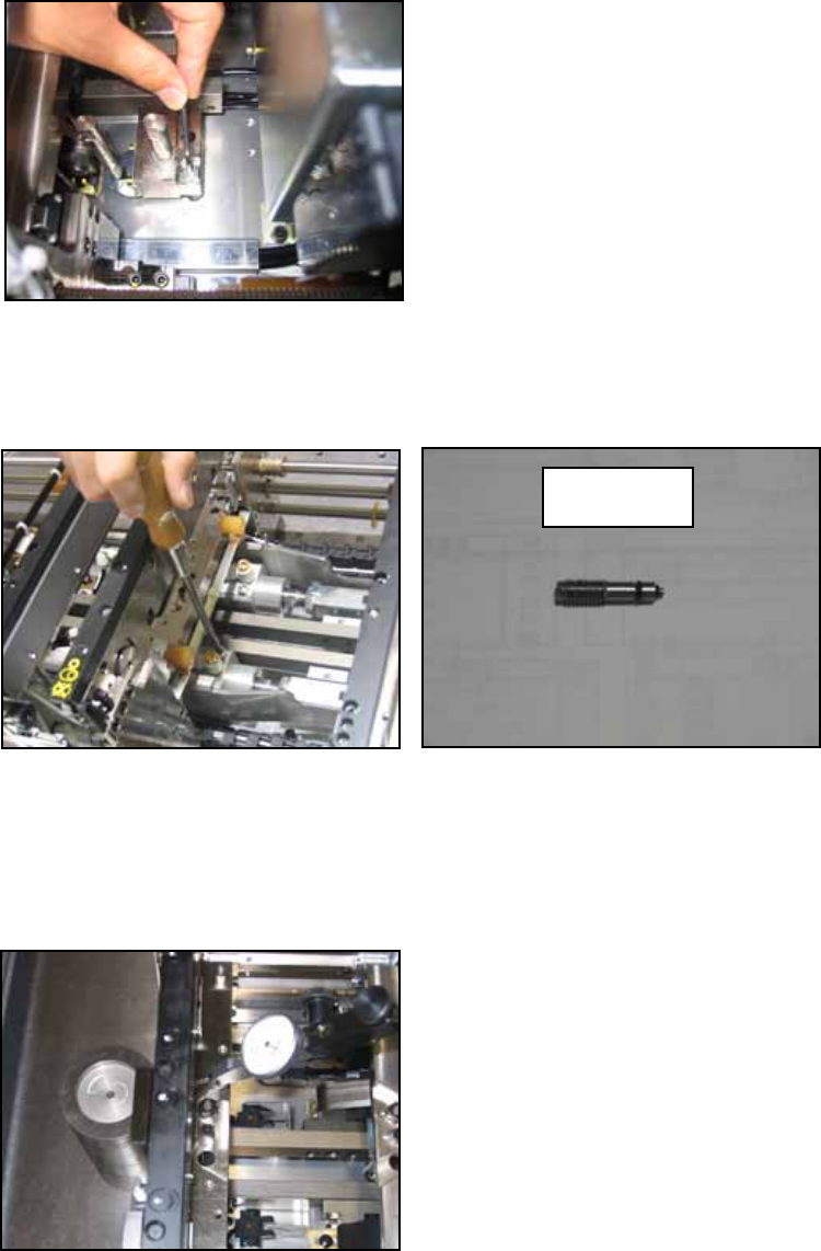
5. Clamper raised position measurement.
Cut the air supply to the machine. Remove the slow clamp speed controller as shown
in the photo below. Fully screw the jig (PZ14950) into the hole where the speed
controller was removed.
6. Supply the air and clamp the conveyor. (Stop at the middle position where clamp high
speed switches to low speed). Set the jig (PM47270) in the parts camera position and
set a dial gage to 0 on the jig.
7. Run the dial gage over the part where the back up plate sits and check that the total
difference in flatness is less than 0.05mm.
PZ14950
NXT Repair Training Textbook
Conveyor Unit
FK-9F98-43-0E
Edition 1.0 9 / 46 FUJI Machine Mfg. Co., Ltd.
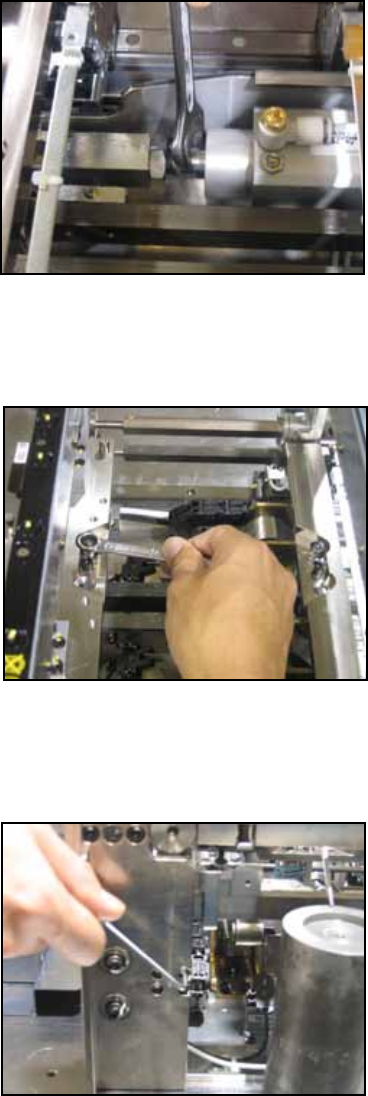
8. If it was out of tolerance loosen the 22mm nut and use a 14mm spanner to rotate the
shaft and set the flatness.
If there is a difference between the reference and secondary rail, loosen the 10mm nut
and move the center shaft to even out the difference. At this time do not move only
one side but move each side halfway towards the other to equalize their height.
To fix any imbalance between the left and right sides loosen the M3 x 4 bolt(s) on the
reverse side of the linear guide. Apply low strength adhesive (Loctite 222) to these
bolts.
NXT Repair Training Textbook
Conveyor Unit
FK-9F98-43-0E
Edition 1.0 10 / 46 FUJI Machine Mfg. Co., Ltd.
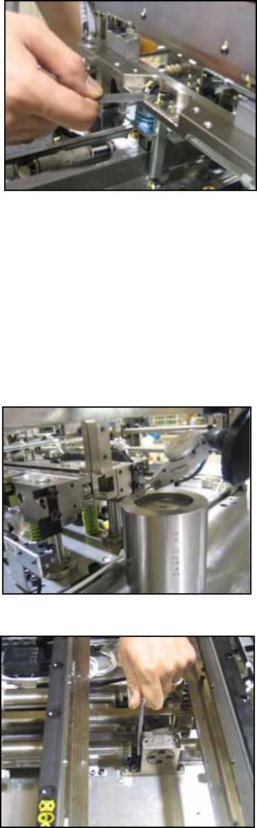
9. As a final check use a 0.3~0.5mm thickness gage as shown in the photo below. Check
whether the push amount is 0 when a board is clamped.
1.5 Conveyor up/down height adjustment (previous M3 and current M6 type)
PM06340 down type 27±0.05 ㎜
PM06330 up type 63±0.05㎜
1. Remove the parts camera and check that there is no rust, then place the jig. Remove
the head and set the jig from which the handle has been removed (AA1TT00). Attach
the dial stand to the jig and set the dial to 0.
2. Measure the lower surface of the cam follower in relation to the jig. Check that it is the
same as the jig (0 ~ 0.1mm).
3. If adjustment is necessary remove the cylinder cover and loosen the 10mm nut.
NXT Repair Training Textbook
Conveyor Unit
FK-9F98-43-0E
Edition 1.0 11 / 46 FUJI Machine Mfg. Co., Ltd.